The planning for the controller is complete and the disassembly of the Nerf gun is done. This is where the real fun begins – modifying the revolver and starting the electronics.
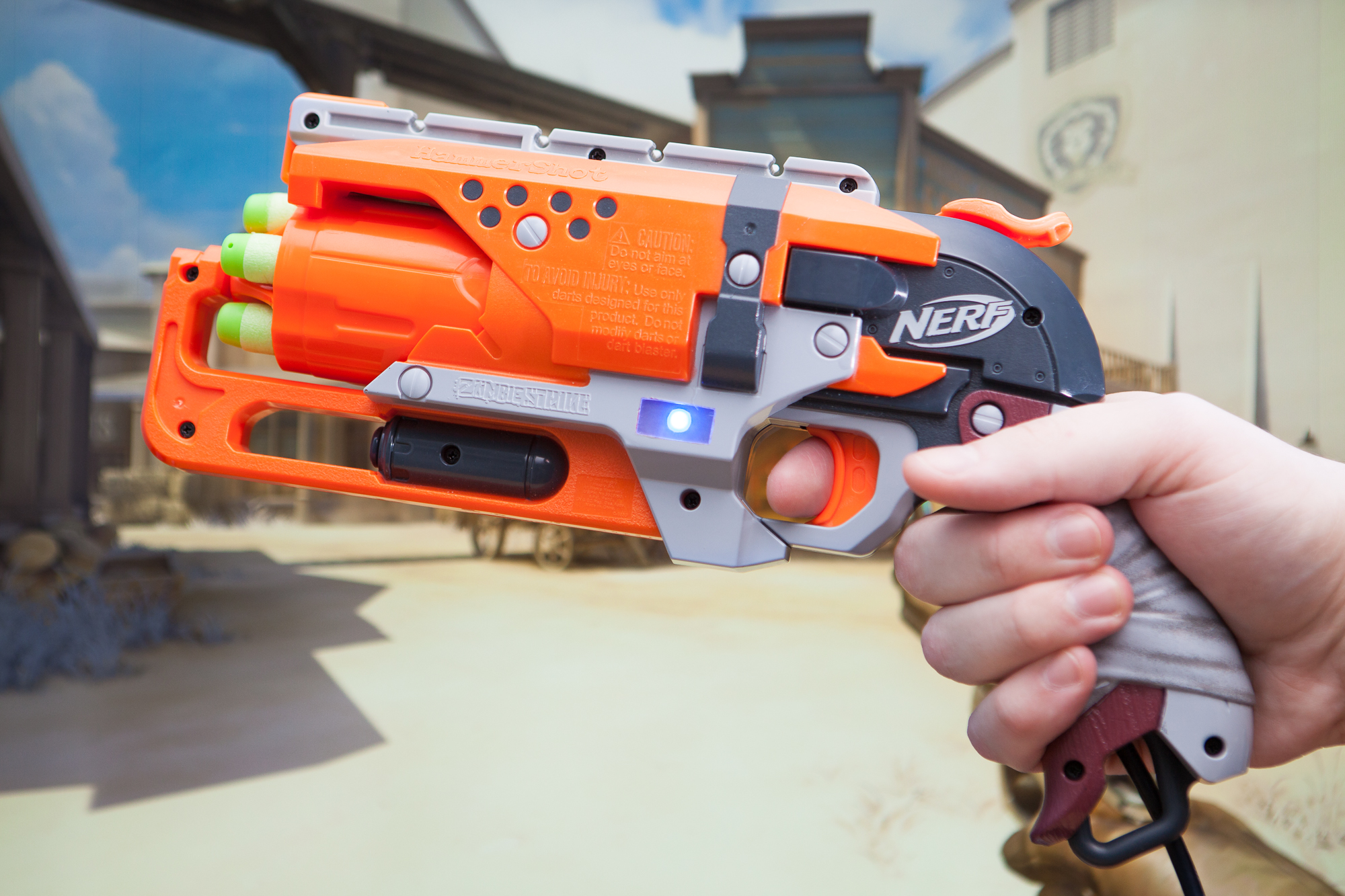
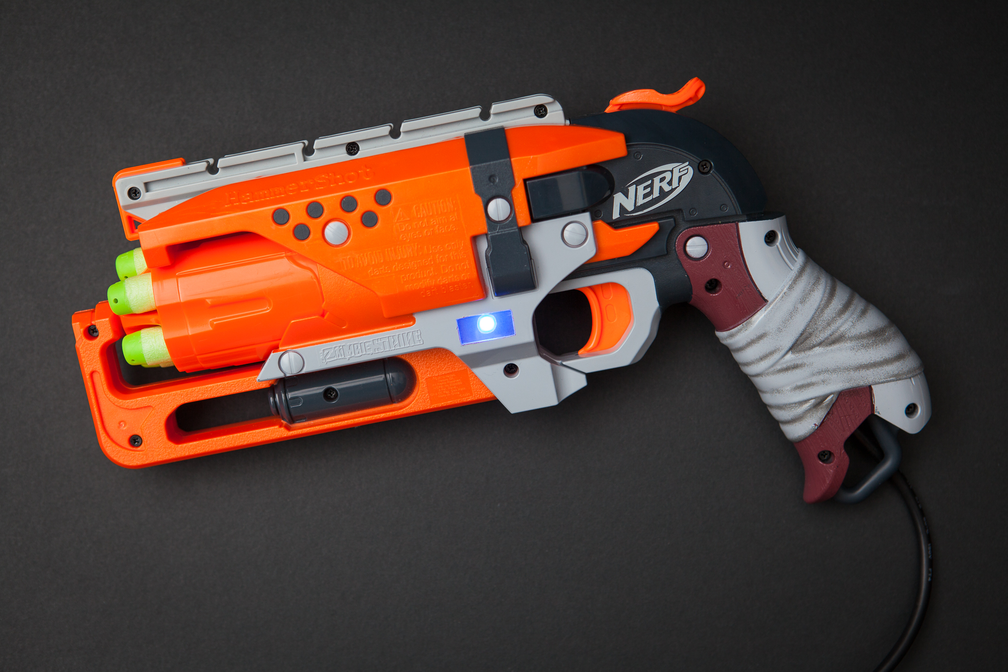
This post is part of a series on creating a custom controller for Overwatch using a Nerf revolver. Check out the project page here.
Nerf Modifications
Before getting to the new parts, there are a few components from the Nerf gun that need to be changed to make these buttons work.
Sear Removal


One of the first steps is to make the hammer and trigger be able to function independently. This requires removing the bit of plastic on the hammer that lets the trigger hold the hammer once it’s cocked. Ten seconds with a cutoff wheel on a Dremel and problem solved!
Spring Force


The stiff spring in place to propel the foam darts needs to be tuned down so I can easily slide the hammer back with my other hand. Although as stock it’s easy-enough to do with my thumb, I want to be able to do it fast like the old West (and like McCree in the game). It’s too stiff for me to pull all the way back with my left hand quickly, so I’m going to lighten the spring (which is now only being used to hold the hammer in place).
Uncompressed, the spring is 2 3/8″ long. It’s ~0.535″ in diameter (although it flares to 0.625″ at the base), and the wire is 0.056″ thick. It’s a hardened steel with a chrome coating, and without making any measurements my technical opinion is that it’s stiff as f#$&.
My first try at slimming the spring was to simply cut the original spring and try stretching it out. Unfortunately even using just half of the original spring was way too stiff to slide it back quickly and easily with my off-hand.
I ended up stopping at my local Mom-and-Pop hardware store and picked up a cheap 3″ steel spring for $1.80 which I then cut down to size. It’s still fairly stiff, but it’s a lot better than the original spring. It’ll have to do.
The Button Plan
There are two dedicated buttons in the pistol: one for firing “normally” (single shots), and one for alternate fire where McCree “fans the hammer” and shoots six shoots quickly. The first ability is going to be wired to the trigger, while the second is going to be wired to the revolver’s hammer.
For both buttons, I’m going to use generic old mini pushbuttons that you would use with a breadboard. Why? Because they’re small, inexpensive, have a solid detent, and most importantly I already have them in hand.
But I do know that these are cheapo-switches and are liable to break at any moment. So I’m going to follow good building practices and make them replaceable by using a separate PCB and mounting bracket for each switch.
Button PCBs
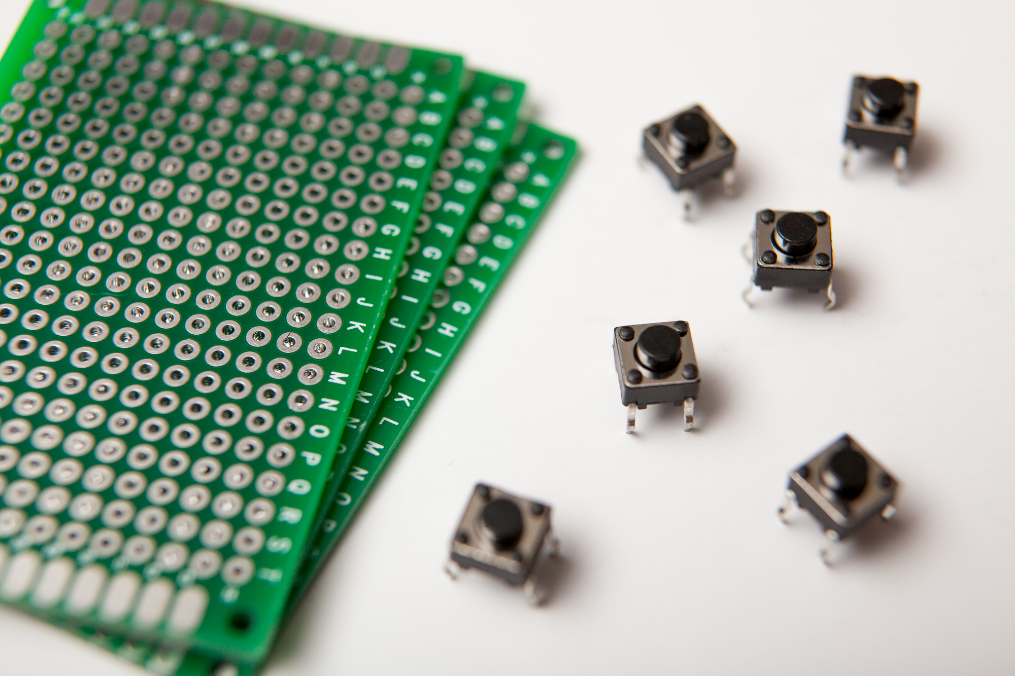
Rather than designing a custom circuit board I’m going to take the easy way out and use some perfboard. It’s not necessarily cheaper than etching my own boards, but it is a lot faster and easier.
The perfboards have their holes at a standard 0.1″ (2.54 mm) pitch. The button legs are roughly 0.3″ x 0.2″, and I extended the width of the circuit board slightly to give me space for the mounting bolts. This leaves me with a board that is 6 holes x 3 holes large – 0.5″ x 0.2″ on centers, or closer to 0.6″ x 0.3″ including the annular rings.
I cut up my perfboards using a pair of straight-cut shears. This leaves a much rougher cut than a Dremel or saw, but produces almost no nasty fiberglass dust. Next, I used a drill bit to expand the outer holes to close fit for an M2 bolt (which did produce a fair amount of dust. Wear your respirator!).
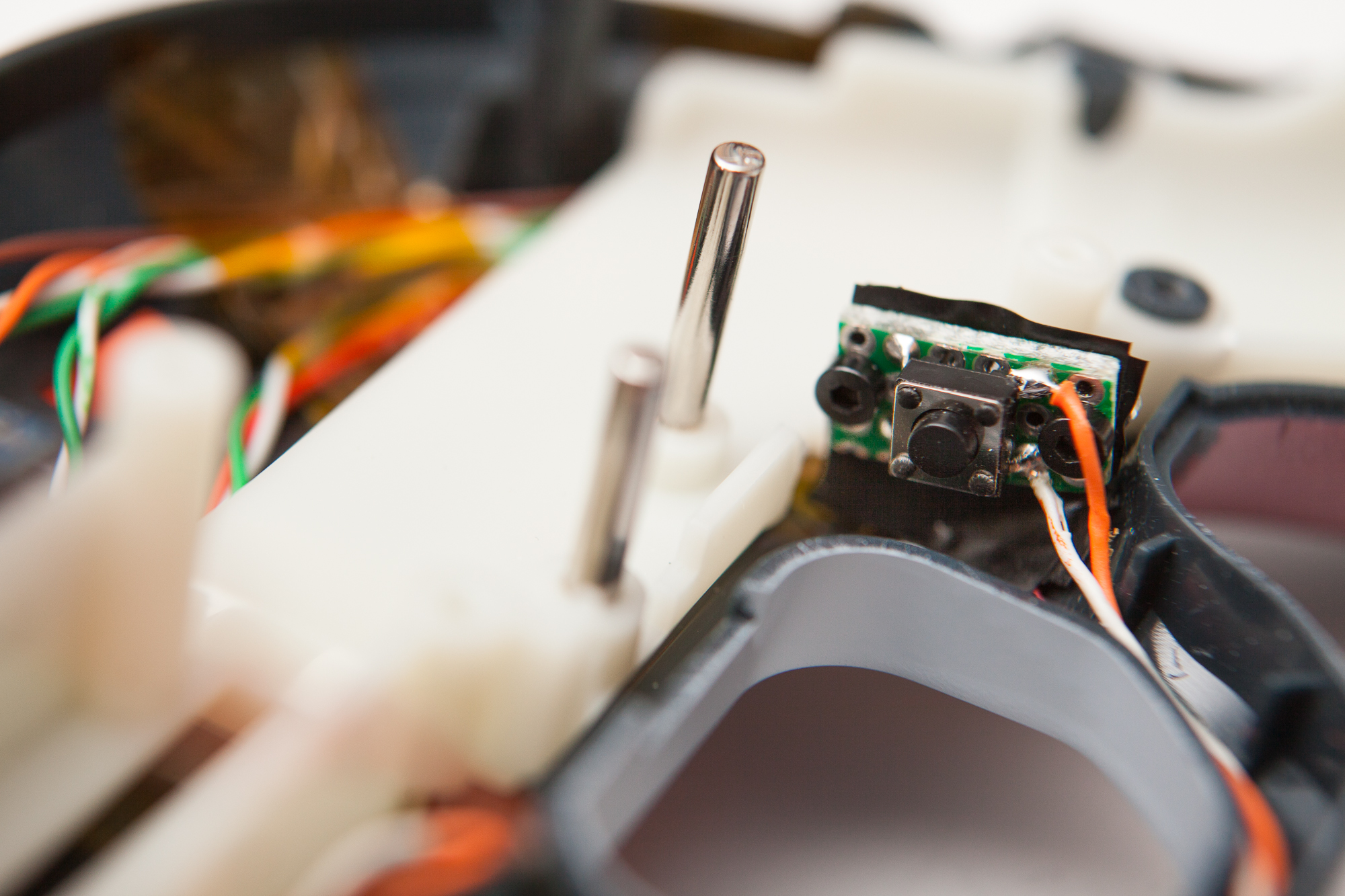
Then it was time for a trip to the soldering station. Four quick joints and the buttons are solidly attached! Now to mount them in the pistol.
Making Mounting Brackets
The ‘L’ mounting brackets for both buttons are going to be made out of sheet metal, which is thin, stiff, and easy to form. I’m going to be using some 0.0359″ (20 GA) mild steel sheet metal that I had lying around from another project.
Button brackets for both the trigger and hammer in place.
I used some paper to test the shape and positioning, then cut the parts out of sheet metal using a pair of straight-cut shears. I measured and then drilled two mounting holes for the PCBs (0.5″ on center) sized for clearance on the M2 bolts, then bent the brackets in a vise using a hammer.
To allow the wires to exit the back of the PCB, I drilled a 3/16″ hole between the mounting points. I then used my shears to make the hole a ‘U’-shaped cutout to the top of the bracket. This makes it possible for the wires to simply slide into the bracket so they won’t need to be pre-run through the hole. (This won’t actually work, and I had to run the wires out the side. See the note at the bottom of this post.)
I gave both brackets a quick once-over with some black spray paint and then took to installing them.
Attaching the Brackets
Each bracket was done separately so that I didn’t have to rush and could carefully hold them still in their positions.
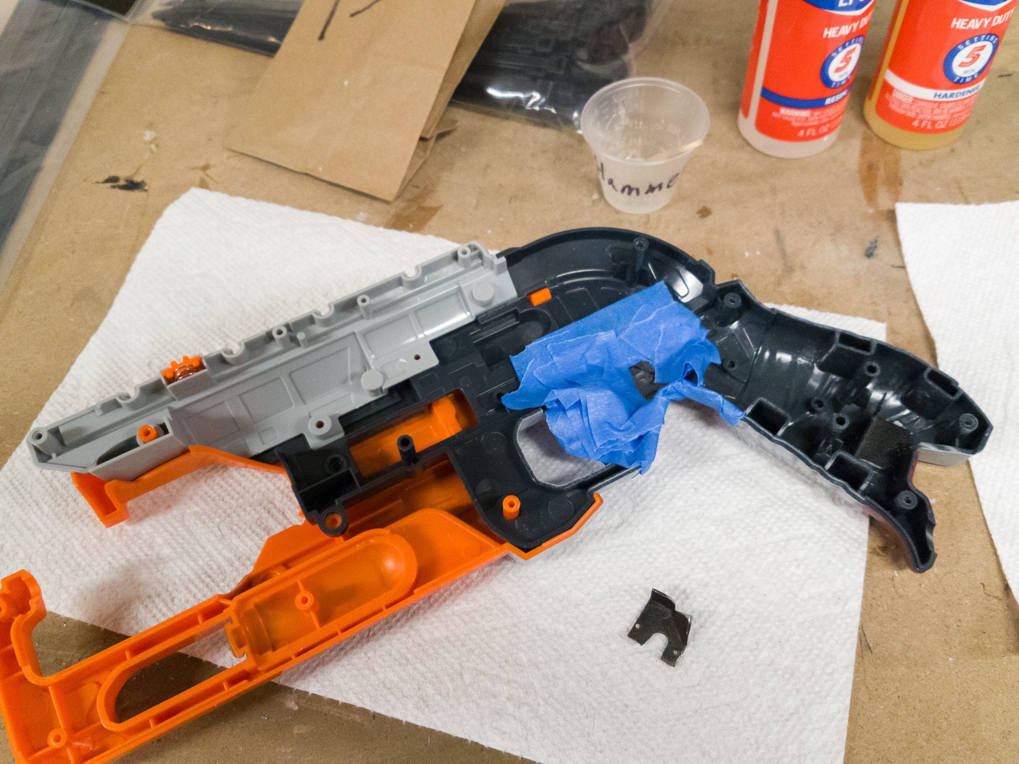
After placing a bracket in its final position I marked the edges and then masked the area with some painter’s tape. I mixed up a batch of 5-minute epoxy, slathered the underside of the bracket and the mating area of the gun, pressed the bracket in place, and held it still until the epoxy started setting-up (3-4 minutes). When the bracket was mostly set, I removed the masking to clear off the excess epoxy.
It took about half an hour for the epoxy to be sufficiently hardened that I could glue the other mount without disturbing it. I let both brackets sit for 24 hours before bolting in the button PCBs.
More Modifications
The trigger bracket had two issues that required modifying the Nerf parts even further.
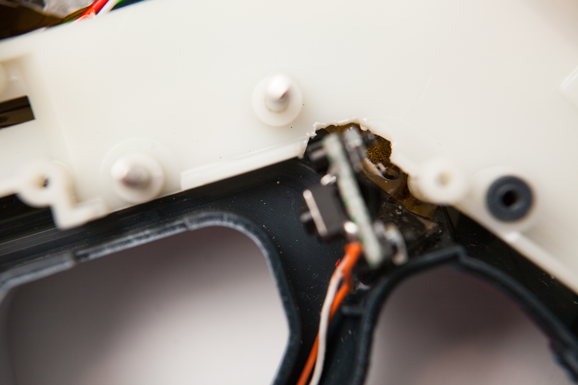 For one, I epoxied it slightly out of position from where I had marked, which was enough to make the white firing bracket not slide only smoothly. The circuit board itself and the nuts used to attach it compounded the problem, so I begrudgingly decided to cut out a notch in the bracket so it slid on smoothly. (After looking at this photo I also went back to clean up that edge.)
The hammer also presented a problem, as pulling it all the way back caused it to push the trigger bracket forward. A few minutes with a Dremel to clear the offending plastic fixed the issue.
Cylinder Rotary Encoder
I thought it would be cool if I could spin the cylinder in order to reload. To do this, I need to wire up a cheap rotary encoder to track the cylinder’s spin.
Encoder Support Fabrication
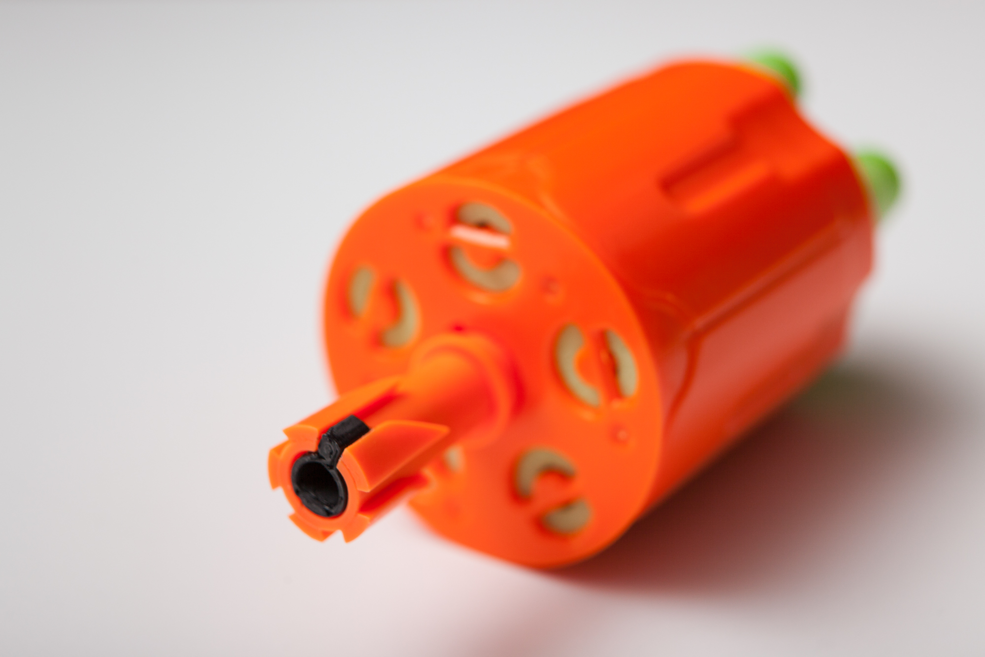
The encoder is going to take the place of that small orange axle piece the cylinder spins on. Unfortunately the mount where the rotary encoder needs to fit does not have enough plastic to support it. So it’s fabrication time!
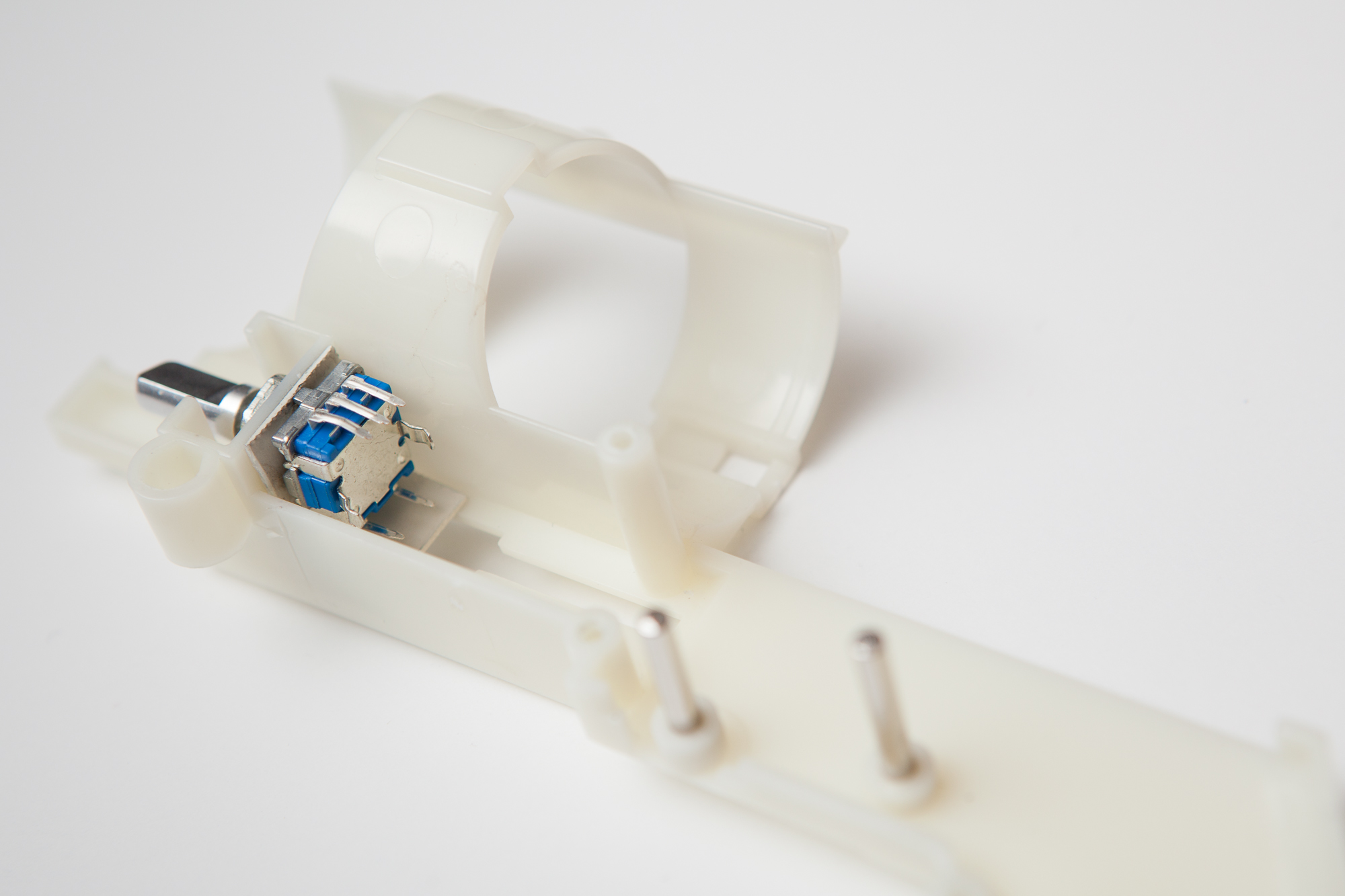
I cut up a piece of that same 0.0359″ steel sheet metal and drilled a hole large enough to fit the rotary encoder (~0.300″). I bent the sheet into an “L”, gave it a quick coat of ivory white spraypaint, and then epoxied it in place with more of that 5-minute epoxy. With the support firmly attached I then carefully drilled out the plastic so the encoder could slide through.
The plastic in front of the encoder mount is too narrow to allow the washer and nut to slide straight on, so they need to be dropped from above when the encoder is installed. I tightened the nut from the front using a pair of needle-nose pliers.
Cylinder Mating
The encoder is mounted, so now I need to connect it to the revolver’s cylinder. The barrel of the encoder fits within the cylinder’s axle, but there is nothing to hold it in place so their rotation is linked. I thought about simply drilling a hole and adding a set screw, but I don’t have any set screws or a tap small enough for it. To the 3D printer!
Using a Dremel, I cut a slot in the cylinder axle between the teeth used for advancing the darts. This is my keying hole.
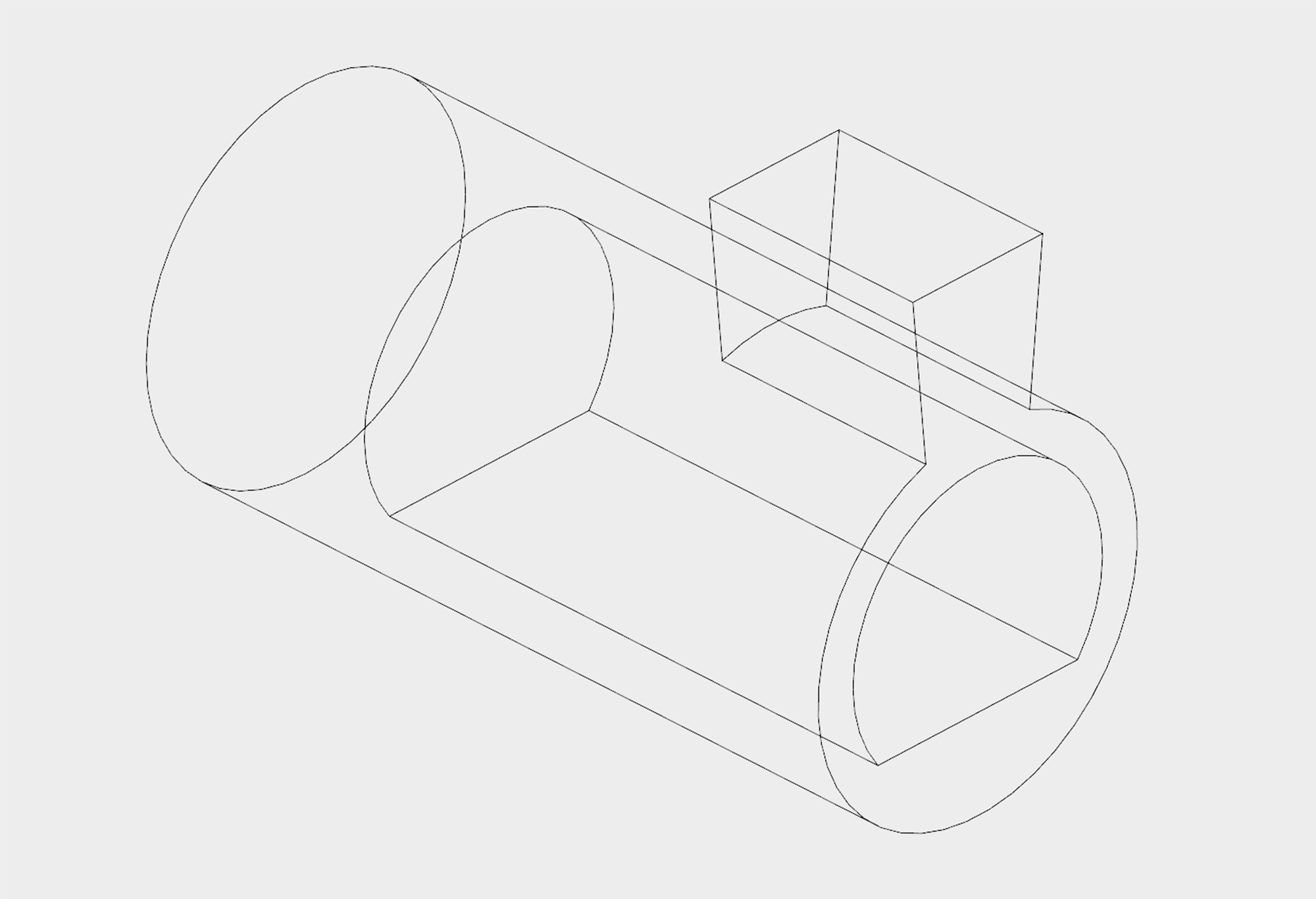 After taking a few measurements with a caliper I threw together a quick and dirty mount in CAD. The mount has a flat for the rotary encoder and a key to mate with the cylinder’s axis. With the key on the cylinder this won’t need any glue, which means if it needs to be tweaked or if it breaks I can replace it.
It took only 8 minutes to print this on my Printbot out of ABS. It slides right into the cylinder and fits the encoder perfectly. No mess, no fuss.
One slight concern is that unlike a set screw this gives little in the way of adjustment for alignment. I couldn’t get the alignment quite right with the encoder nut, so I had to add a small 0.030″ plastic shim to the encoder for the final assembly. It looks bad, but the cylinder spins easily with little resistance.
Conclusion
The buttons and rotary encoder are in place and working! I’ve tested each of them separately, but I’m going to save the wiring until everything is in place within the shell.
Next Post: RGB Indicator LED and Capacitive Touch Sensor (Part 3)
An Aside: Metal and Electricity
As I wrote above, I originally created a slot in the back of each bracket for the wires to exit from the button circuit board. This didn’t end up working out.
For one, the brackets are made of steel… which conducts electricity. I knew this, so I gave them a coat of paint. However when I attached the button my multimeter showed that it was shorted, so I had to improvise. I cut a small piece of electrical tape and stuck it between the PCB and the bracket. This, also, did not work.
It turned out that the solder points on the back of the circuit board were sharp enough to pierce the electrical tape and bridge the button’s connection when tightening the board into its bracket. I eventually desoldered the wires from the back, grinded the back of the PCB until it was flat, and ran the wires out the side. With no solder points to pierce it, a small piece of electrical tape was enough to prevent the button from shorting.
If I had a pre-made PCB with solder connections in the center this wouldn’t have been an issue. Just a little hiccup with doing things the quick and dirty way.