The McCree controller is done! Now it’s time to take a break and do a little postmortem: what worked well, what didn’t, and what I would do differently next time.
This post is part of a series on creating a custom controller for Overwatch using a Nerf revolver. Check out the project page here.
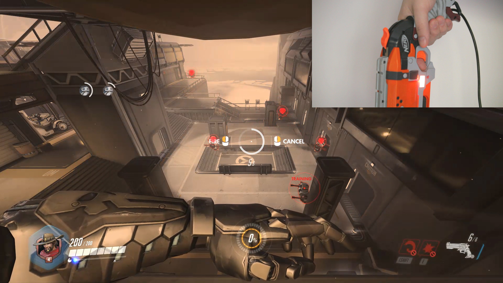
Overview Video
Now that the controller is done, I’ve made a short video summarizing how it works. Enjoy!
Software Download
Now that everything is finalized, I’ve also uploaded all of the code and 3D printed designs to GitHub if you’d like to make your own Hammershot controller. You can find the repository here.
Things Learned
As much as anything else this blog is meant to be a learning exercise – pushing my comfort zone when it comes to making things and documenting how it goes. To that extent this was pushing my comfort zone in a different way than usual. Rather than being careful and working with parts or techniques that were new to me, I tried to do this project as fast as possible using only things that I had on hand (with minor exceptions). You wouldn’t know it by looking at the project posts, but I had the controller’s hardware almost completely done before I even started the documentation.
Because of this, most of the things I did while building were quite familiar: working with metal and plastic sheet, 3D printing, epoxying, drilling, soldering, etc. etc. I did learn a bit about how the internals of rotary encoders work, as well as the very basics of capacitive sensing.
The programming side was also well-trodden for the most part, although I did learn quite a bit about how to work with IMUs. Notably how the IMU represents its data and how to manipulate the various scales to get the numbers how I needed them (degrees per second, degree change, degrees as represented by mouse ticks, etc.). With all of the sign manipulation I also got signed integer type ranges hammered into my head (2size – 1 for the negative, 2size – 1 – 1 for the positive). I also learned what the C++ ternary operator is and how to use it.
Since I ended up swapping out the dance pad for a Wii Nunchuk, I learned a fair bit about how to work with Wii extension controllers. This includes the connector pinout, data ranges, and I2C formatting.
What Worked Well
If I were to do this again, what would I keep the same? Usually this is the shorter of the two lists!
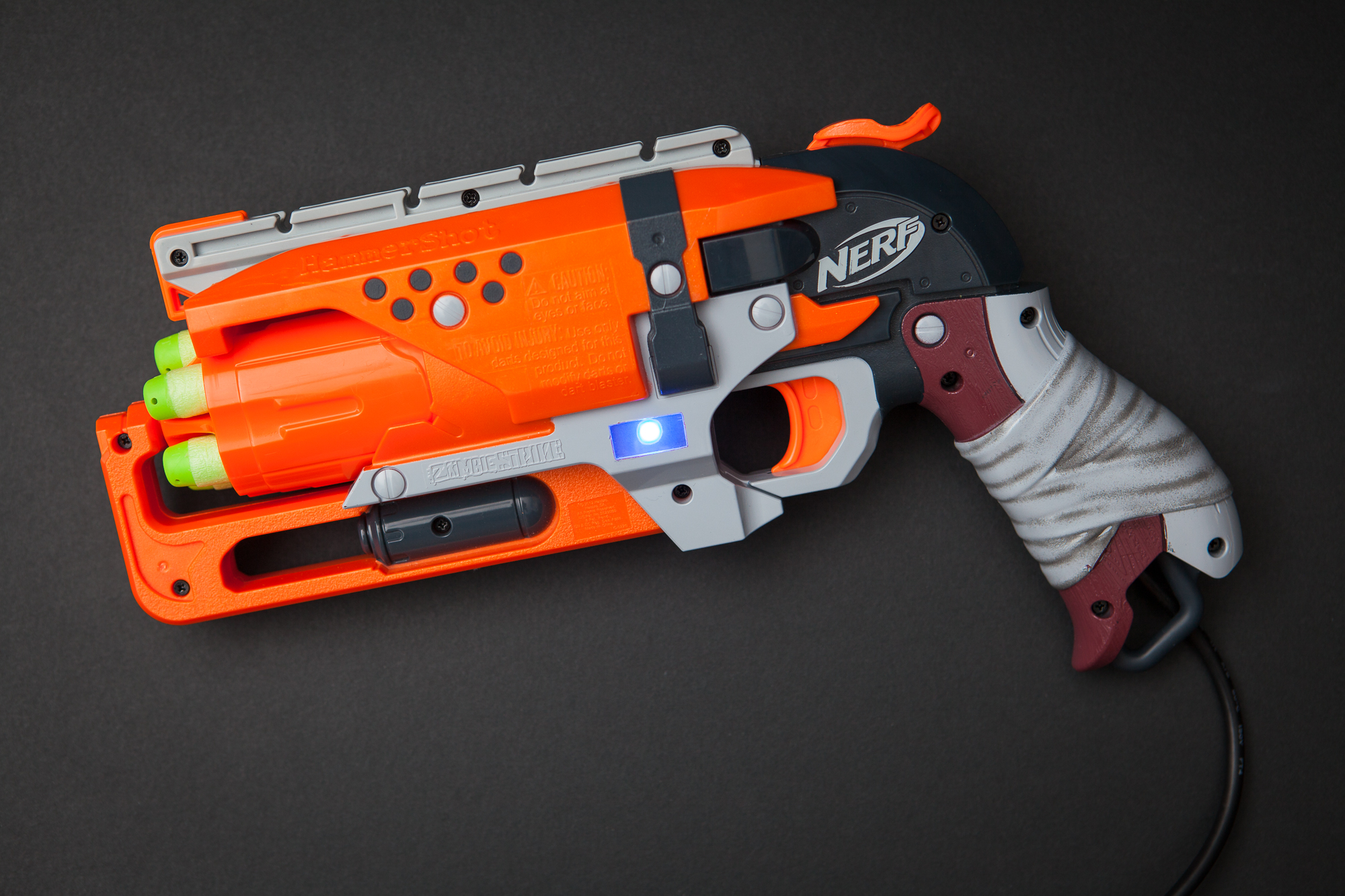
Controller Building
With rare exception, just about everything in the Nerf gun build went great. There was never a point where my original plan didn’t work out and I had to re-do something. There are a couple of things that I would have done slightly differently, but if I built this again with the parts I have on hand I think 99% of it would be exactly the same. So put down “just about everything” under this heading.
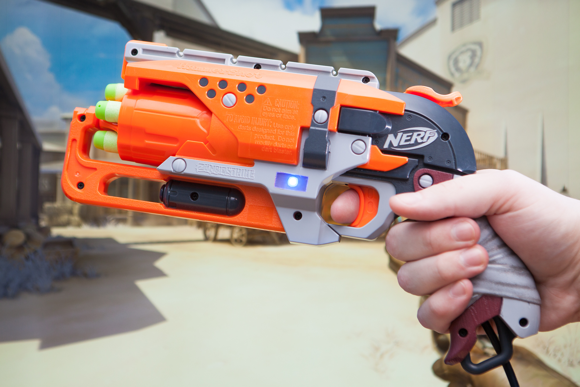
Indicator LED
To be a little more specific, I think adding the indicator LED to the side of the controller was one of my better ideas. Not only is it incredibly useful for debugging, but it also provides useful feedback while playing: are my button presses registering, is the capacitive sensor stuck on, etc. etc. It also looks really slick behind the flush-mounted window.
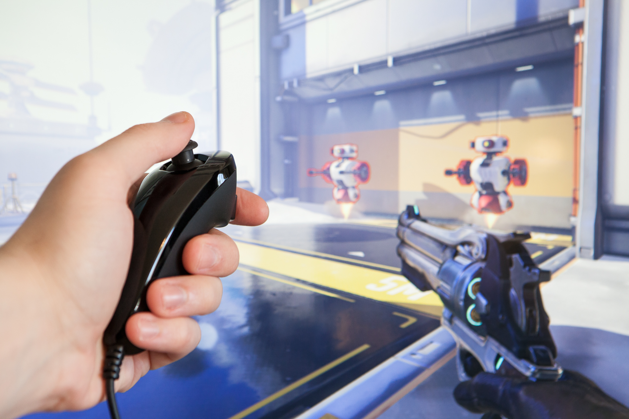
Control Mapping
The controls for the Nerf gun worked even better than I had hoped, and I really like the logical separation between the “aiming” and “movement” controls being on the Nerf gun and Nunchuk, respectively. After taking the first few minutes to get acquainted, everything was quite intuitive to use. I would keep these all exactly the same.
Gyroscope Aiming
Although I had a lot of problems getting this to work, the final version of the gyroscope aiming is really smooth and accurate while still letting me move fast enough to navigate the map.
Capacitive Sensor
The thing that takes the aiming from “good” to “great” is the capacitive sensor. The controller often gets pointed in strange directions trying to hit a target, and this allows me to quickly and easily correct back to center without missing a beat. Making the sensor capacitive means that it’s completely hidden and very fast to use. 10/10 would black magic again.
Nunchuk Movement
As I said in its dedicated post, the Nunchuk movement works so well it almost feels like cheating. I initially felt a little guilty about this, but the point of the project is to play the game with the Nerf gun, not to make it unnecessarily harder. The Nunchuk is only a part of what makes this possible.
What Didn’t
If I were to do this again, what would I absolutely change? This is usually the longer of the two lists…
Wire Thickness
This is my one and only big gripe with the build itself. Because of how the internals are organized, there is a thick bundle of 10 wires running through the Nerf gun’s grip underneath the firing bracket. These wires don’t all fit flush underneath the bracket, and require a bit of coaxing to get the two halves of the shell to close completely.
If there is a next time, I might try either combining wires (there’s three grounds in that bundle) or routing the wires another way. For instance the LED wires run through the grip because there’s space for the connector, but they could also run directly across from the circuit board. I just needed to think four three-dimensionally. I could also try as the heading says and just use smaller wire.
PCB Design
The circuit board has a few small design flaws that should be addressed:
#1: I2C Pull-Ups
This is just an outright oversight. I’m not sure if the MPU6050 breakout board has I2C pull-ups on it, but if not I should have included them on the circuit board. It should still be fine with only the one device and I haven’t noticed any issues with the IMU not registering, but it’s an oversight nonetheless.
#2: Rotary Encoder Crosstalk
As I’ve mentioned previously, the rotary encoder has some crosstalk with the capacitive sensor’s traces. Twisting the rotary encoder (cylinder) quickly causes the sensor to read at a higher baseline. The wires are no-where near each-other, but the traces for the encoder and the capacitive antenna run together on the PCB. Next time these should be moved further apart.
#3 Interrupt Pins
I did not take full advantage of the interrupt-capable pins available on the Pro Micro. The buttons and one of the encoder pins run to non-interrupt pins on the board which require polling. At the end of the day this isn’t a big deal because both reading the capacitive sensor and writing to the LED require disabling interrupts, but still. If I were to change out the circuit board, having interrupt-capable pins mapped would improve performance.
Things I Might Do Differently
Lastly: what isn’t necessarily good or bad, but I still might think about changing next time around.
Plastic Button Mounts
The sheet metal button mounts inside of the controller work fine, but they bend a bit which can make the controls feel a tinge squishy. If I built another controller I might try using cast plastic mounts, contoured to the geometry inside of the shell. They would likely be stiffer and easier to install (albeit more work up-front).
Relative Gyroscope Aiming & Capacitive Sensor
I went back and forth on this one, but I think it needs to be included. While I’m quite happy with how the gyroscope aiming turned out, I can’t help feel that my perspective on it is a bit skewed. Am I satisfied with it because it’s the ideal setup, or am I satisfied with it because my earlier iterations were so abysmal?
The gyroscope aiming in the final controller is relative, meaning that it ignores the ‘0’ position of the screen and sends inputs based on rotational change per sample. Next time I’d try adding a magnetometer, which would give me an absolute yaw reference and allow movements based around the monitor as an origin.
With that setup I could also in theory do away with the capacitive sensor. While the capacitive sensor does work, it can be finicky at times and requires constant recalibration. Doing away with it altogether might be easier for the player, too.
Adding Wireless
I made this controller wired for a few different reasons, mostly having to do with the logistics of dealing with an onboard battery and my lack of knowledge regarding Bluetooth. Still, I think making the controller wireless would be a huge step-up.
Conclusion
Although it was a little shaky in the middle there, this was a lot of fun to make. It’s quite satisfying to do things like fan the hammer and use McCree’s ultimate by mimicking the in-game animations, and the final version of the controller actually plays quite well.
I think I’ll probably end up doing some more “AltCtrl” projects at some point. It’s fun to try to figure-out different and quirky ways to play a game. It’s also a nice self-contained project that comes with its own benchmark for what is “good” – how difficult the “AltCtrl” version is to use relative to the “normal” way you would play the game.
For the time being though, this project is DONE. Another one on the books!
1 Comment
Charles K. · December 5, 2021 at 8:36 pm
Fun project! You need to check out Gun4ir if you enjoy actual lightun shooters. DIY lets you use any gun shell from Nerfs to actual arcade guns and uses an arduino for it’s main component. Requires a few leds around the screen but aim is dead on and an easy project for a guy with your background.