Once the LED strip has been soldered together and attached behind the monitor, the next step is to configure the software on the PC. The communication protocol for Adalight is quite simple, which means there is a variety of PC software that can send color information to the Arduino. There are other options, but the two I’ll cover are Processing and Prismatik.
Processing
Processing is what Adafruit used in their original Adalight setup. Processing is not a standalone ambilight software package, but in fact a media-oriented development environment based on Java.
To get Processing working, you need to download the 2.2 IDE (Adafruit says users have reported problems with newer versions) from the processing.org website here. You will also need the Adalight sketch from Adafruit’s Github repository.
Setup for the Processing sketch is a bit complicated. If the Arduino’s serial port isn’t the first in the serial list, you’ll need to find and change the index number after Serial.list(). On my system the Adalight device uses the second serial port, so I needed to change the index number from “0” to “1”.
port = new Serial(this, Serial.list()[1], 115200);
You’ll also need to set up the number of LEDs and their positions. This is done in two places: a display array and a per-LED array. These keep track of the total number of LEDs on an XY coordinate plane, as well as their respective positions. For the individual LEDs order matters: the first LED listed is the one that receives data first. On my system that’s the LED in the bottom-right, closest to the monitor stand.
These are the parameters for my setup:
static final int displays[][] = new int[][] {
   {0,32,18} // Screen 0, 32 LEDs across, 18 LEDs down
static final int leds[][] = new int[][] {
   {0,24,17}, {0,25,17}, {0,26,17}, //7 LEDs on the bottom right
   {0,27,17}, {0,28,17}, {0,29,17},
   {0,30,17},

   {0,31,17}, {0,31,16}, {0,31,15}, //18 LEDs on the right edge
   {0,31,14}, {0,31,13}, {0,31,12},
   {0,31,11}, {0,31,10}, {0,31,9},
   {0,31,8},  {0,31,7},  {0,31,6},
   {0,31,5},  {0,31,4},  {0,31,3},
   {0,31,2},  {0,31,1},  {0,31,0},

   {0,30,0},  {0,29,0},  {0,28,0},  //30 LEDs across the top
   {0,27,0},  {0,26,0},  {0,25,0},
   {0,24,0},  {0,23,0},  {0,22,0},
   {0,21,0},  {0,20,0},  {0,19,0},
   {0,18,0},  {0,17,0},  {0,16,0},
   {0,15,0},  {0,14,0},  {0,13,0},
   {0,12,0},  {0,11,0},  {0,10,0},
   {0,9,0},   {0,8,0},   {0,7,0},
   {0,6,0},   {0,5,0},   {0,4,0},
   {0,3,0},   {0,2,0},   {0,1,0},

   {0,0,0},   {0,0,1},   {0,0,2},   //18 LEDs on the left edge
   {0,0,3},   {0,0,4},   {0,0,5},
   {0,0,6},   {0,0,7},   {0,0,8},
   {0,0,9},   {0,0,10},  {0,0,11},
   {0,0,12},  {0,0,13},  {0,0,14},
   {0,0,15},  {0,0,16},  {0,0,17},

   {0,1,17},  {0,2,17},  {0,3,17},  //7 LEDs on the bottom left
   {0,4,17},  {0,5,17},  {0,6,17},
   {0,7,17}};
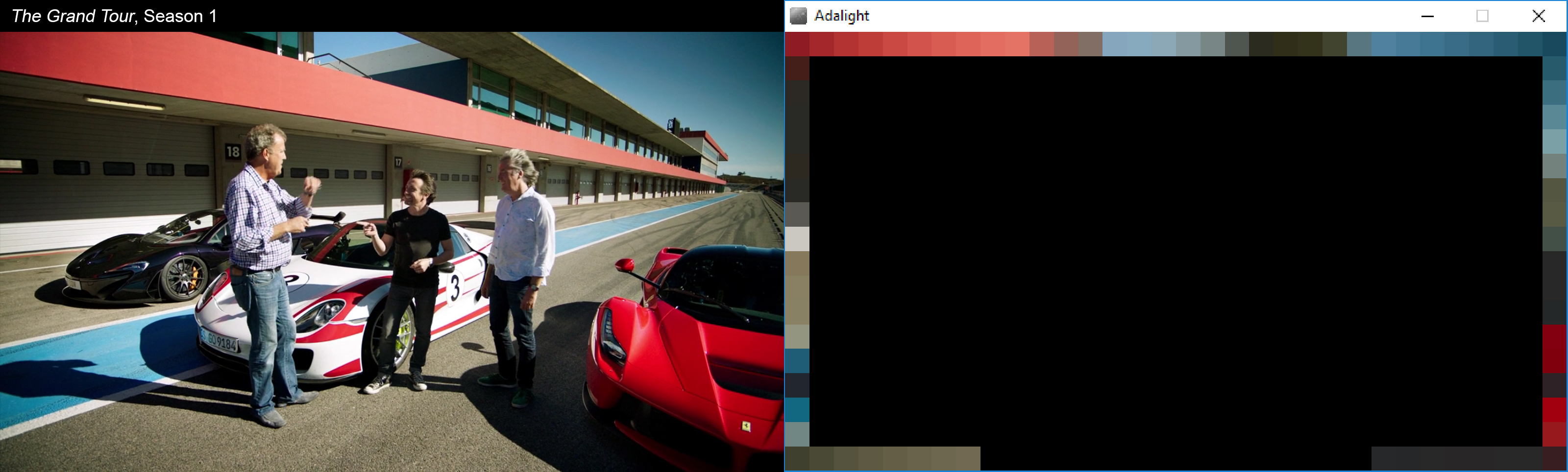
With the serial port and LEDs configured, press the “Run” button in the top left and the program will start pushing data. I was expecting it to be clunky, but to my surprise it works quite well. The Processing sketch includes both a debug framerate and a display pane that tells you the colors of every given LED and their position. I tried a few different programs, including a movie and a fullscreen video game. All of them worked flawlessly with no tweaks.
That’s about the extent of the good news. The bad news is that the Processing sketch is fairly barebones – it only has a few configuration options, and it has no way to set color balance, gamma, or over-brightening. Worse than that, it’s a resource hog: for 20 frames per second, the application used an average of 12% of my CPU and 200MB of RAM.
Processing is a development environment, so I have no doubt that if you spent considerable time rewriting the Adalight code you could improve its efficiency and add the missing features. Though as an off the shelf solution it leaves a lot to be desired.
Prismatik
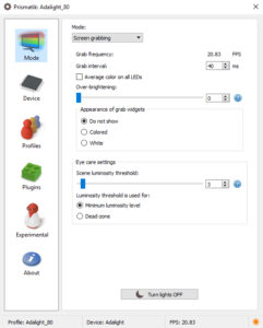
Enter Prismatik – an open-source software for ambilight devices that works with Adalight. Compared to the Processing sketch, Prismatik has many more configuration options including more advanced darkness compensation, gamma correction, and the ability to set color balance. It’s also significantly more lightweight: using less than 1% of my CPU and fewer than 40MB of RAM to produce the same framerate as the Processing sketch.
You can download Lightpack’s Prismatik from their website here, though I would recommend another version. Prismatik is open source software, and one user named Patrick Siegler decided he could improve it, adding features such as DirectX grabbing, 64 bit support, and an audio visualizer. He also incorporated the Windows Desktop Duplicator API for color grabbing, which he says significantly increases performance.
Having compared both builds, I’ve found that Patrick’s version works much better. You can find downloads for both the installer and source files at the forked Github repository here. As of this post, the current version is 5.11.2.11.
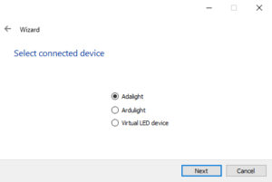
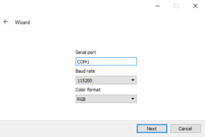
Configuring Prismatik is a snap. Under the “Device” category there is a configuration wizard. Set the serial options, RGB color format (remember that the Arduino takes care of the GRB transformation for the WS2812B LEDs), and then arrange the LEDs and capture zones. For my setup the auto arrangement in the “Andromeda” pattern works almost perfectly. You can also chose “Cassiopeia” if you have no LEDs on the bottom edge, or “Pegasus” if you have none on either the top or bottom. Patrick Siegler’s version added a “Custom” arrangement option, where you can set the number of LEDs in each segment (top, side, bottom), capture width, and set a gap for stand width at the bottom.
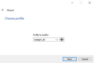
My custom 80-pixel setup on my Dell S2415H is as follows:
Top:          30
Sides:        18
Bottom:       14
Thickness:    15%
Stand Width:  52%
Start Offset: 0
Once you click “Finish” your lights should click on! Easy! The software isn’t without its bugs – the lights don’t always reflect the current profile, and the “on/off” button occasionally glitches out. But by and large, it’s a big improvement over the Processing sketch.
Conclusion
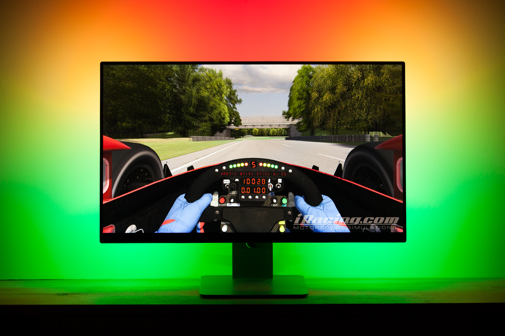
With basic configuration done in either Processing or Prismatik, the ambilight is working! Play with the LEDs for a bit – drag a window around the screen, load up a colorful video, or play a game. Don’t be afraid to tweak things if they seem off (e.g. if an LED is in the wrong position, or the LEDs display green when there is red on the screen). In Processing you can stop the code and make updates, and in Prismatik you can re-run the configuration wizard at any time. If your lights aren’t working, make sure the LEDs have power, you selected the right serial port, and in Prismatik that the lights are turned “on”. If you see flickering, try another USB cable or another USB port.
This post is part of a series on creating a DIY ambilight using Adalight and WS2812B LEDs. Check out the project page here.
Next up: Part 4 – Calibrating Ambilight Color in Prismatik
An Aside: AmbiBox
When I was doing my research for this post I came across AmbiBox, a program which came recommended by a number of people. I tried both AmbiBox 2.1.7 and AmbiBox 2.1.0, and neither worked well. The software was clunky, slow to respond to inputs, and either threw errors or crashed when setting the pixel configuration. It’s possible these issues were permissions-related due to not running the program as administrator, but a blind exe provided by a Russian developer with “tons of features” and no documentation that needs admin permissions sets off alarm bells for me. If you’re successfully using AmbiBox with Adalight more power too you – but I’m not interested.

16 Comments
Dmitry · March 2, 2018 at 8:30 am
Hi! I’m currently building 78 led strip Ambilight for my MacBook Pro 15″ 2017 with screen size 2880×1800 221 ppi and using Prismatik 5.11.2.13 (by psieg) I can’t configure the screen size capture correctly, it maps to a smaller size: 1680×1056 px in the top left screen corner, so I get only this screen area mapped and displayed on the led strip. Is it a problem in Prismatik app running it on High Sierra OS? I didn’t find the solution to this issue, so I really hope you could help me with this, so looking forward for your reply!
Btw, I’v managed to power my 78 led strip and send signals to Arduino Nano just via one USB-C port (5V 3A max) on MacBook which is really cool because I don’t need any additional external power adapters for the strip.
Dmitry
Dave · March 2, 2018 at 9:53 pm
Unfortunately I can’t help. That sounds like an issue with Prismatik itself, I’d recommend creating an issue on GitHub.
Dmitry · March 3, 2018 at 10:14 am
Ok, thanks, already did!
Konrad · September 9, 2018 at 9:37 am
Hello, It’s me again.
I’ve been reading through the steps and what i need software wise and i’m kind of confused. There are mentions here of Adalight, Processing, Prismatik… but not all of it is required?
Correct me if I’m wrong but for the end result, all i need is from software:
– your modded Adalight firmware with fastLED
– Arduino IDE to program the Arduino with Adalight firmware
– Prismatik as control software
and thats it?
Konrad · September 9, 2018 at 9:41 am
oh, and the FastLED Library itself too
Dave · September 9, 2018 at 1:36 pm
This post specifically is comparing driver software: the Processing IDE with the Adalight software vs Prismatik. You’ll need some sort of driving software running at all times to send the colors to the LEDs. I prefer Prismatik. You do not need both.
To set up the Arduino you will need:
-The Arduino IDE
-The FastLED library
-A copy of my modified Adalight firmware
Once the Arduino is programmed you can uninstall the Arduino IDE and FastLED.
Konrad · September 18, 2018 at 2:30 pm
Hello Sir, It’s me again
I assembled my own Ambient Light thanks to you, it works 😀
I have one question tho, did you get the “Sound Visualisation” mode to work? I’m trying to turn it on but no matter how i mess with settings the led’s light up and nothing happens as i play audio.
Dave · September 18, 2018 at 6:48 pm
Yup, works fine for me although I never use it. I have to use the “Loopback” feature of my device and it takes 10-15 seconds for the LEDs to adjust to the sound level and kick in.
Elek · January 3, 2019 at 8:22 am
When I try to run the sketch in processing I always get an error at: “c = pxls[offs[o]];” it’s line 364 for me but I have less leds. I configured everything right because they didn’t have errors. (I have a ws2811 led strip which is 12v and I’ve put the capacitor the arduino and the cables on a piece of perfboard and they all work because I’ve tested out them with a little program that I downloaded.)
Elek · January 3, 2019 at 8:33 am
Oh and the error message is: “ArrayIndexOutOfBoundsException: 5047685”
Elek · January 3, 2019 at 9:13 am
I’ve got it to work, I gave the coordinates mirrored and when I wrote them the other way it worked
Naman Garg · September 17, 2020 at 7:57 am
Can it work with non-addressable RGB led strip, like a 5050 LED strip
Dave · September 17, 2020 at 11:51 am
Technically yes, although you’ll only get one color at a time.
Cristian · February 7, 2021 at 7:48 pm
Hi!
I read your articles with great interest, I’m preparing for my own Ambilight project.
Do you think a LED strip with *30* LEDs/m would be “too sparse” or way too dim?
It has the obvious advantages of less power draw and less CPU cycles.
Thanks!
Michal · March 28, 2022 at 8:53 am
Hi, I like you project, its almost what I have in mind – what I am searching is using ws2812 or any other kind to play pictures throught led matrix. You sure know LED tube projects most of them works with preprogram lights in program, but you work with Prismatik witch live play colors from monitor to led strip in real time. And what I need is 8 Tube lights which works like your left and right part of monitor and display 1/8 of monitor from left to right.
Can you help me with this topic please? What will be great is upgradable Prismatik where can be set number of Collums with leds in there.
Dave · March 30, 2022 at 9:02 am
Hi Michal. From your description it sounds like Prismatik will work just fine. You will need to place the “grabbing zones” manually across the monitor, either by hand or by modifying the text file that specifies their positions.
Otherwise, Prismatik is open source! You can always fork the software and develop your own upgrades.