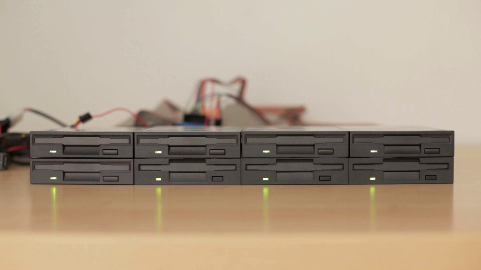
So far, I’ve figured out how to get a single floppy drive to make music. But why play music on one floppy drive when you could play it on eight?
An Arduino Uno with Moppy can drive a maximum of nine drives when connecting directly to the I/O pins. If you have nine drives on hand and an Arduino Uno, it’s simply a matter of connecting the data lines to the Arduino (step, direction, and drive select), and the power lines to a 5V supply.
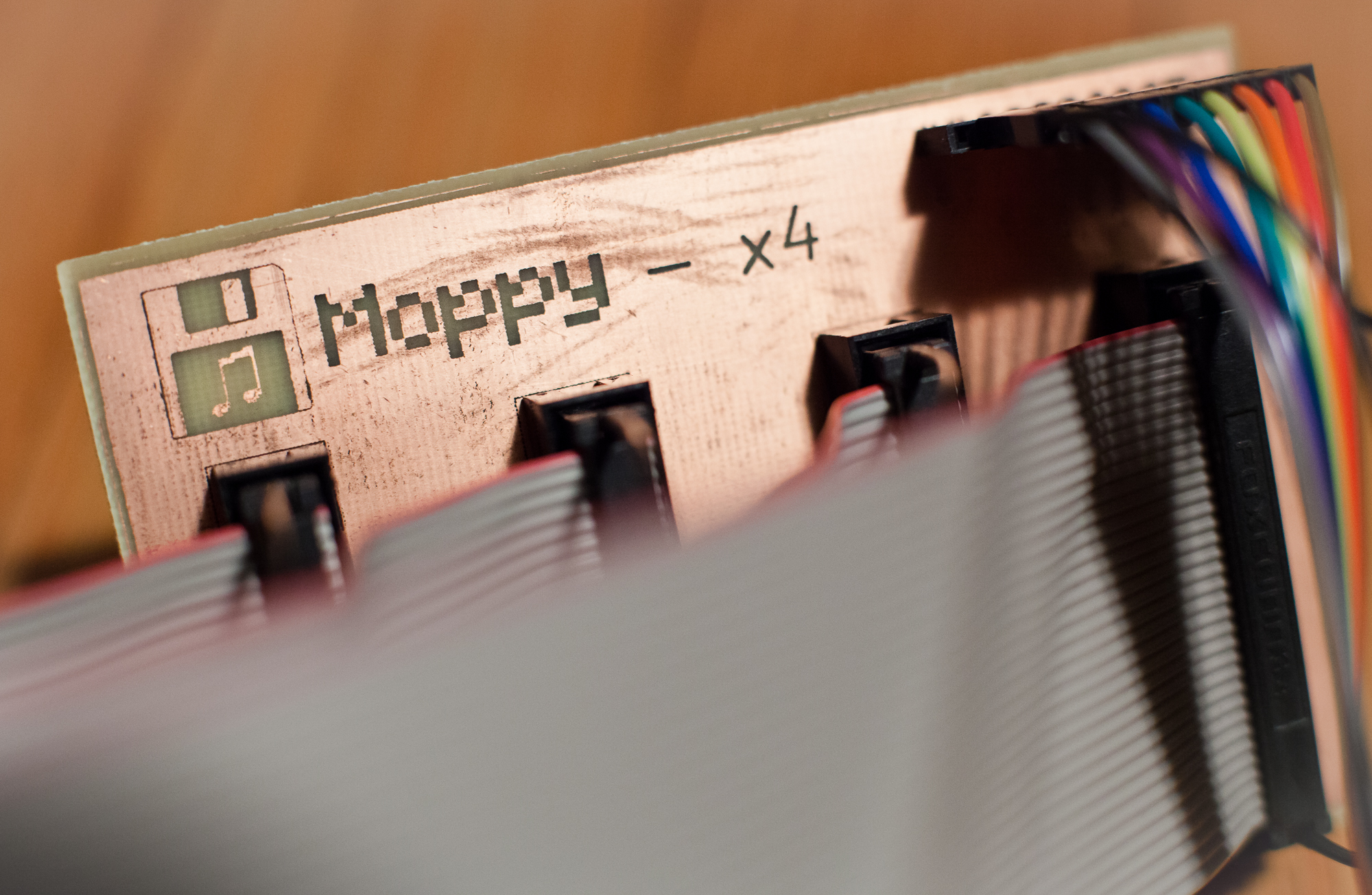
That’s the simple and messy way. The more complicated, cleaner way is to build dedicated custom power cables that fit the floppy drives, and custom circuit boards to connect to pre-made 34-pin IDC cables.
I prefer the cleaner way, so I decided to build my own floppy power cables.
Planning
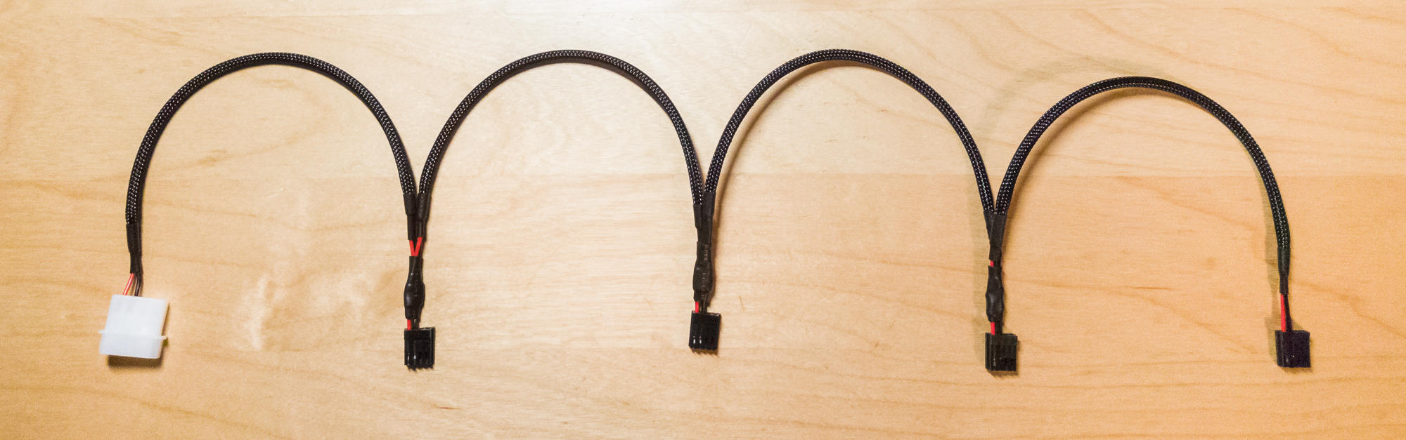
I’m looking to control eight drives in total, so I decided on building two identical ‘1 to 4’ daisy-chained cables to keep things simple. I went with a daisy-chain layout because the floppy power requirements are low (~0.5 A each) and it makes splicing simpler.
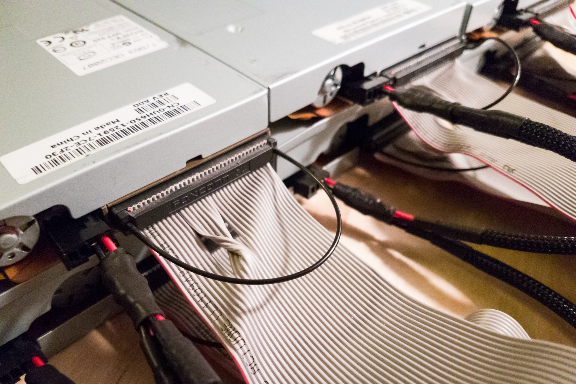
Floppy drives use a 4-pin Berg connector for power, which includes +5V, two ground wires, and +12V (pins 1-4, respectively). For just driving the read head stepper motor, the drives only need +5V and ground. +12V isn’t used, which cuts the number of wires needed in half.
So far I’ve been using a PC power supply, which has more than enough power on its +5V rail. The source ends of the cable will have 4-pin Molex connectors to connect to the supply.
Originally I wanted to try stuffing two wires into each pin and avoid doing any splicing, but the sockets for the floppy drive connectors are too small to fit two 22 AWG wires without cutting strands. Parallel splices it is!
I was fortunate to have most of the parts and all of the tools on hand, otherwise I probably wouldn’t have bothered building these cables. Taking into account the price of the tools, a terminal strip would have been messier to use but significantly less expensive.
Supplies
- 22 AWG Stranded Wire (Red / Black) – (4 lengths of ~11″ per color, per cable)
- Parallel splices (6 per cable)
- Berg connectors (1 per drive)
- Berg connector sockets (2 per drive)
- Molex 4-pin male connectors (1 per cable)
- Molex 4-pin male pins (2 per cable)
- 1/8″ expandable polyester sleeving (4 lengths of ~8″ per cable)
- 5 mm heat shrink (for the sheathing ends)
- 3.5 mm heat shrink (to cover the splices)
- 7 mm heat shrink (to cover the completed splices + sheathing)
Tools
In my opinion, the dedicated crimper is 100% necessary. It works perfectly with both the floppy and Molex pins, and a generic crimping tool just didn’t cut it (although a standard crimper is needed for the splices).
Please note that some of these are Amazon affiliate links which help fund the content on this site. Thank you for your support!
Process
This is my first time building spliced “PC” cables, so what I did is probably not the ideal method but it worked for me.
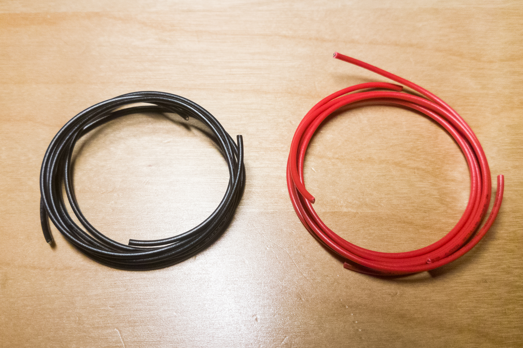 First, I cut the wires to length. For my “1 to 4″ daisy-chained cables, I needed one length between each drive and one length to go to the source connection. That gave me 4 wires per net (4 power, 4 ground). I put two drives next to each-other and ballparked the lengths at ~11” each.
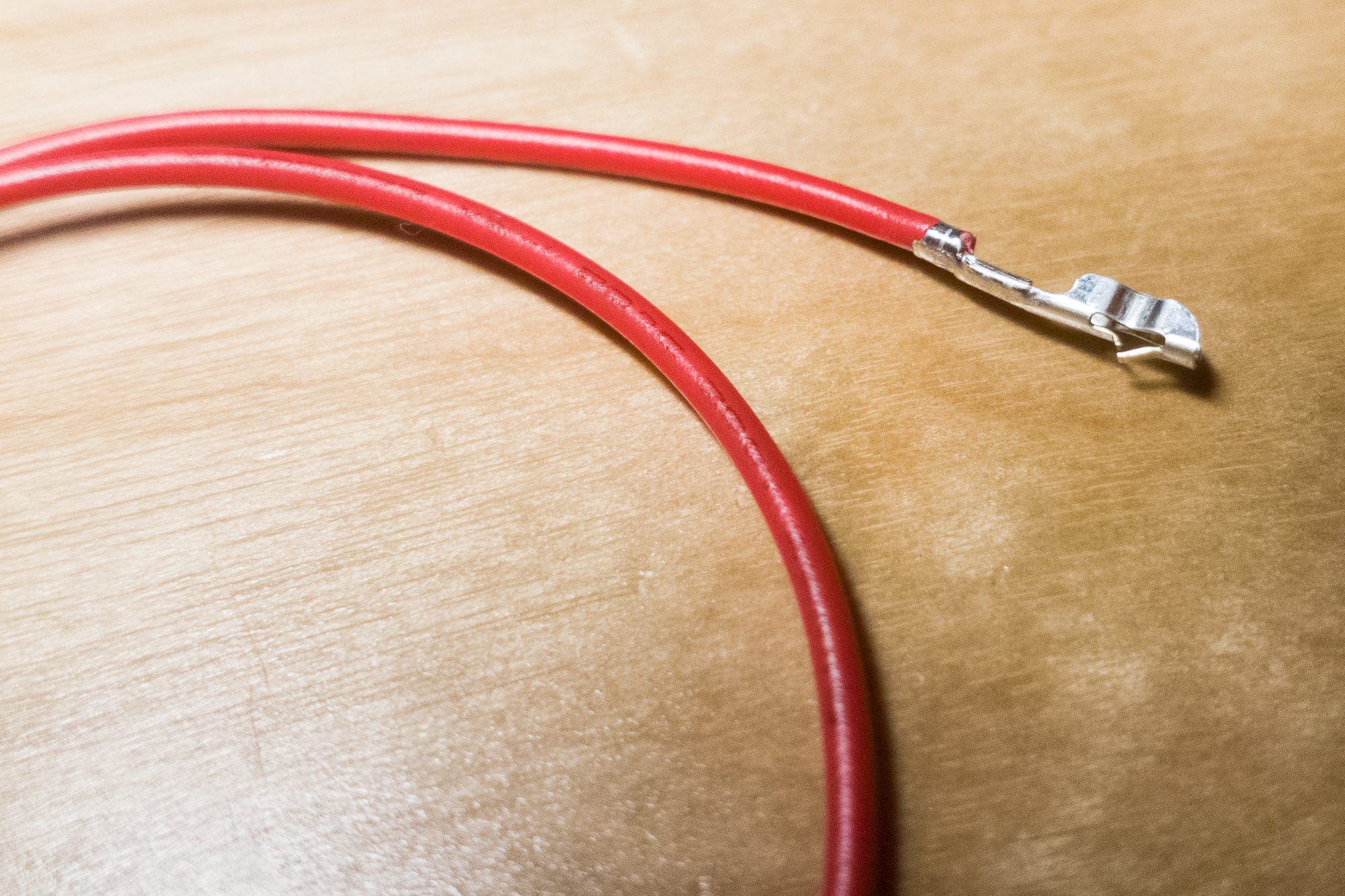 Next, I stripped one end of every wire ~1/8″ and crimped on a floppy connector socket.
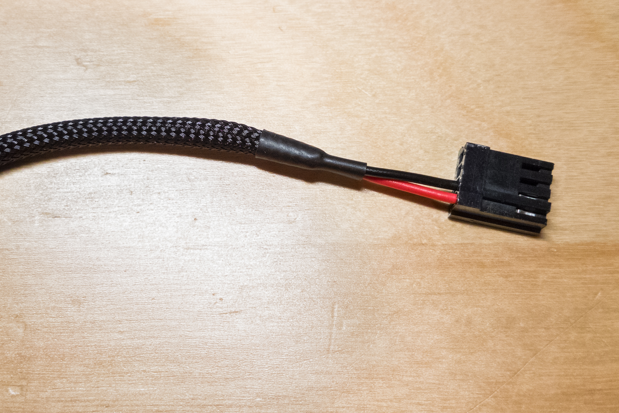 The wires on the end of the cable aren’t spliced, so they were inserted directly into a Berg connector and the wires were covered in sleeving. The ends of the sleeving were secured with 5 mm heat shrink.
For the rest of the wires: I slipped on a parallel splice over the insulation and marked its position next to the socket, with a bit of breathing room to ensure it ‘snapped’ into the connector. For these cables, the close end of the splice was approximately 7/8″ from the tip of the socket.
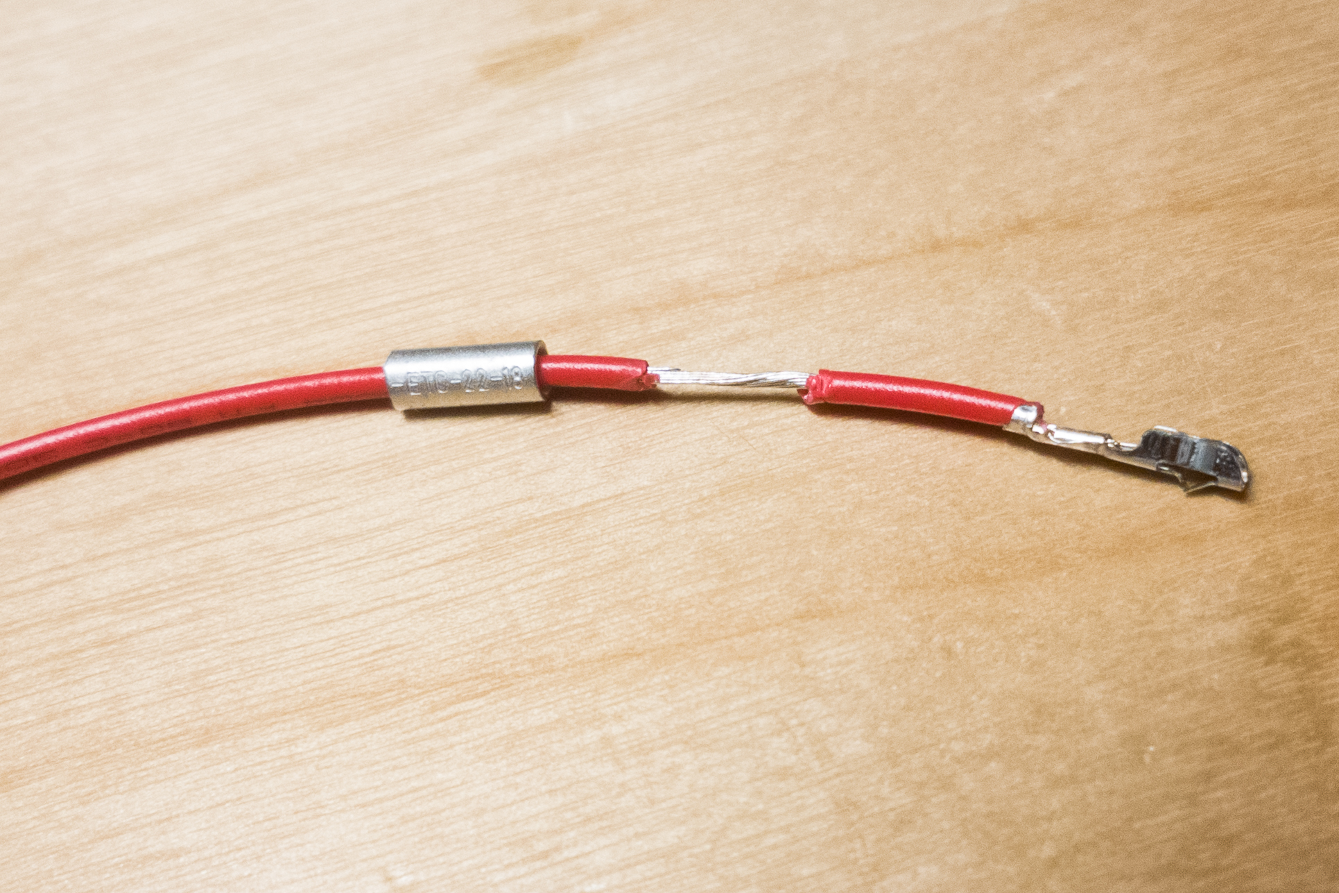 I moved the splice down the wire and very carefully used a utility knife to remove the insulation where the splice will sit. Heat shrink will cover this area, so it’s more important that you don’t cut any stands and that the splice make secure contact than that the insulation is cut cleanly.
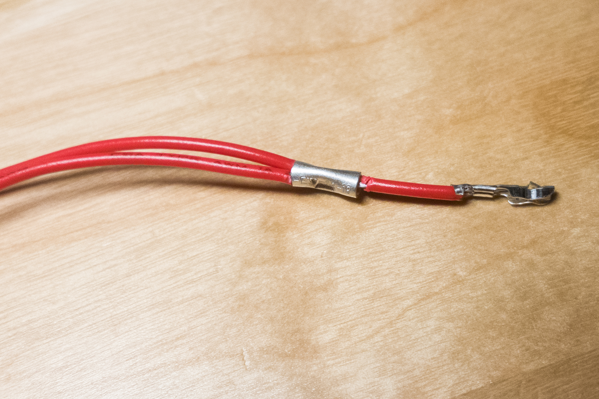 After sliding the splice back over the newly bare wire, I stripped the non-crimped end of the sleeved wires from to the length of the splice, inserted it into the back end of the splice, and crimped everything together using a standard crimper.
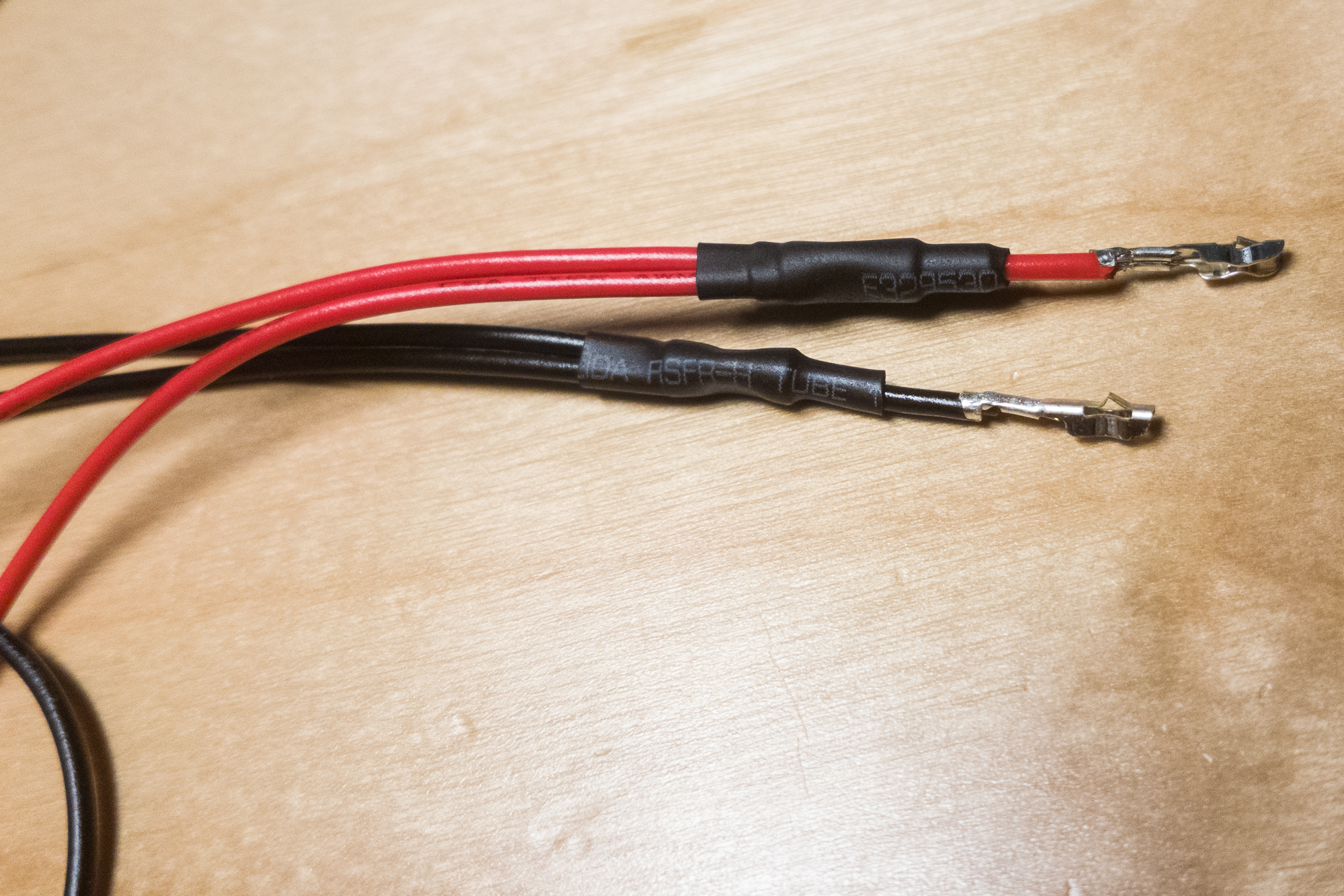 I used 3.5 mm heat shrink to electrically isolate the power and ground splices from each-other, and then put 7 mm heat shrink over the pair to keep them stable. The crimped sockets were then inserted into a Berg connector.
Wash, rinse, repeat for each leg of the cable. On the last portion, I added the Molex pins/connector rather than the Berg connector so the cable can source power from a PC power supply.
With everything in place, I checked the continuity for all of the connections and checked for shorts between power and ground.
Conclusion
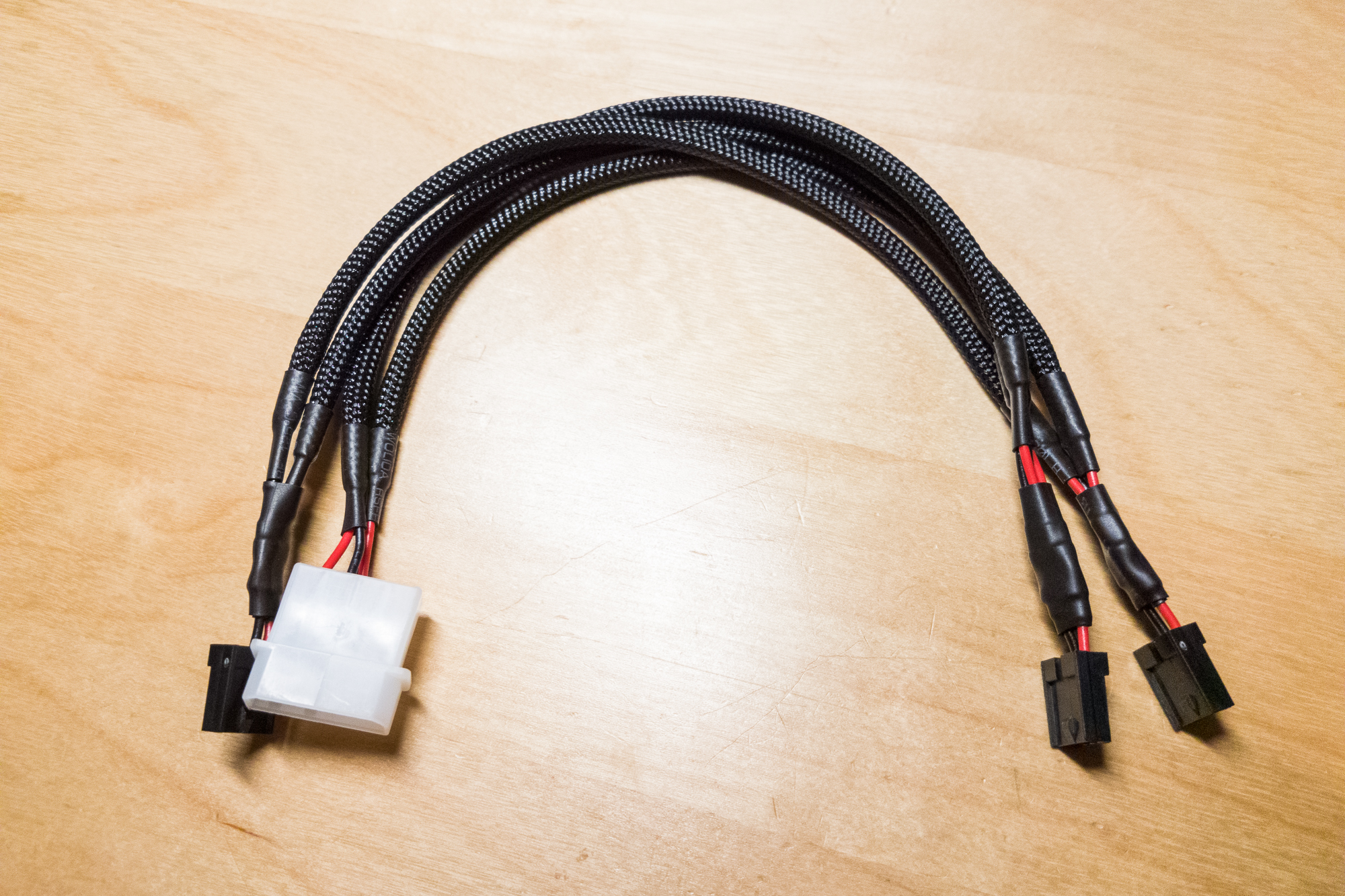
If I ever build an enclosure for these drives I’ll eventually have to remake these cables without the loops, but for now they work great. They slide on and off the floppy drives quickly and I don’t have to worry about accidental shorts or polarity problems when moving things around.