The first step in taking the Arduino-based ‘ambilight’ from concept to completion is to modify the LED strip so it fits nicely around the monitor. Like most addressable LEDs, the 5m roll I’m using has cut lines where you can trim it. Because each pixel is its own self-contained circuit, you can arrange them in any shape or number you can think of so long as you connect the three wires: power, ground, and data.
This post is part of a series on creating a DIY ambilight using Adalight and WS2812B LEDs. Check out the project page here.
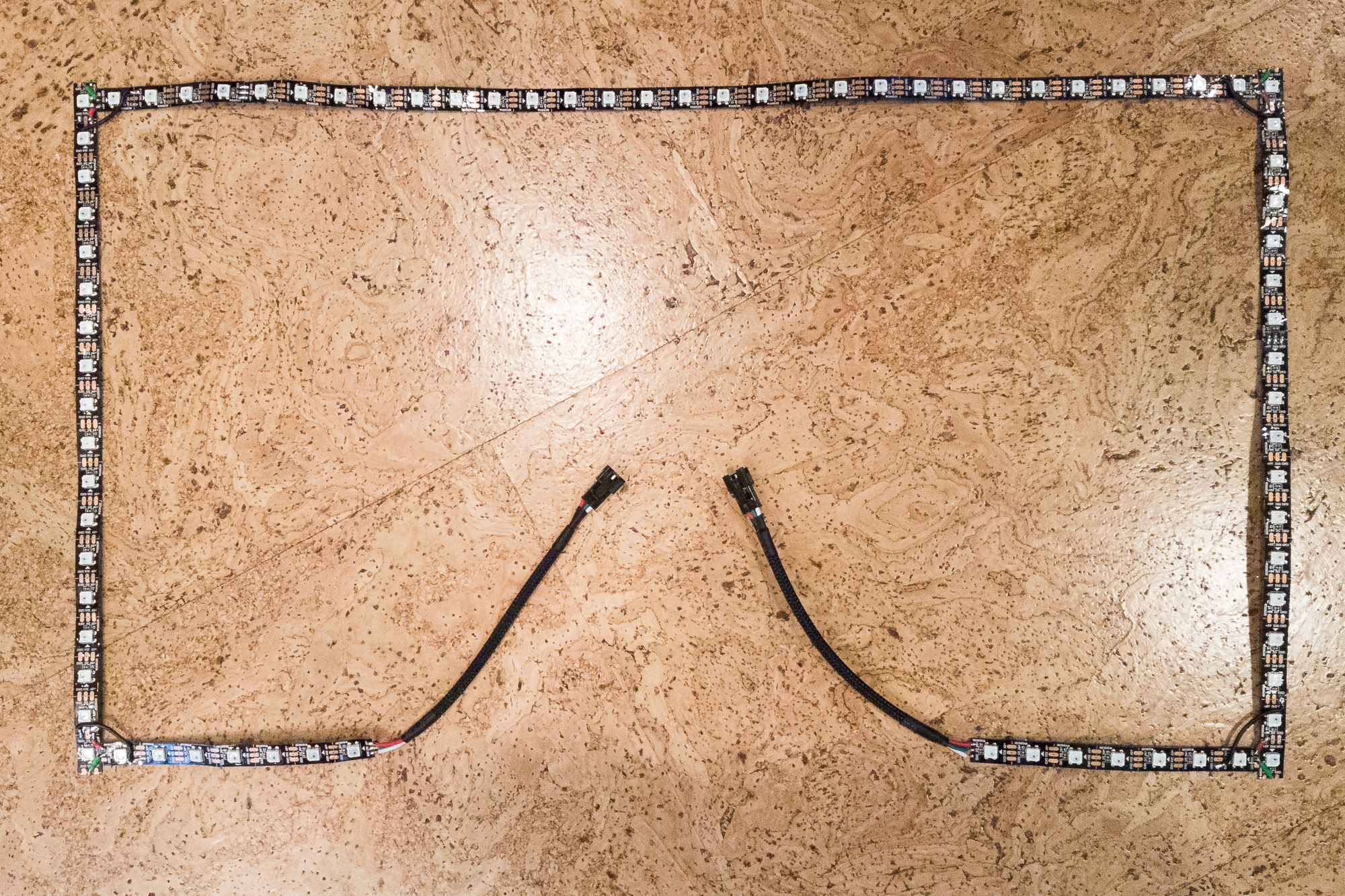
To start I disconnected the monitor and laid it face-down on a soft towel. I unrolled part of my WS2812B strip and started measuring. The plan is to leave about a half inch between the LEDs and the monitor edge, to account for wires and light spill. The easiest way to arrange the strips is end-to-end, leaving a gap in the corners for the wires. I wanted an LED in the corner, so I took the slightly more difficult path of having the edges butt up against each-other with the side strips as the primaries.
On my 24″ monitor, I’m using 7 LEDs on each side of the bottom edge, 18 LEDs on each side (including the corners), and a single 30 LED strip along the top. This gives me a nice round number of 80 total LEDs. (In hindsight I probably should have used one fewer LED for each of the bottom strips and then added an anchor for strain relief on the cables. More on that later.)
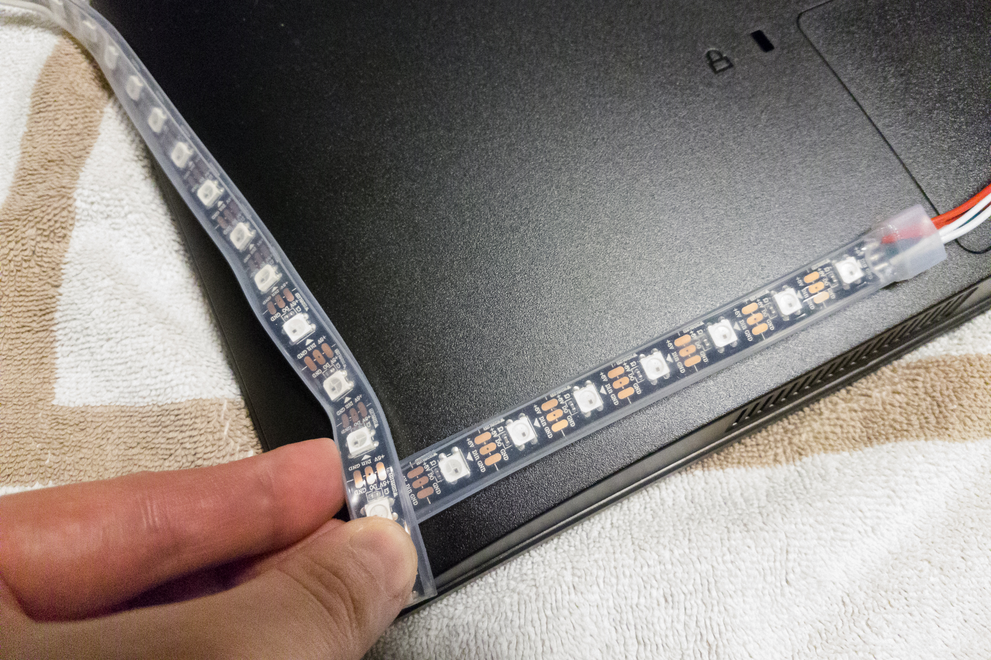
Once I had all of my strips cut, the next step was to take off the waterproof sheathing. The roll I ordered uses IP67 waterproofing, where the LED strip is encased in a silicone tube. I didn’t need the waterproofing for this project, but it’s easy to remove and the price was the same. I wouldn’t recommend keeping the waterproofing regardless – the silicone makes the strip difficult to mount, blocks some of the light output, and prevents the strips from staying flat. The strip is loosely sitting inside the sheathing, so a firm pull is all you need to separate them. I ended up cutting off the first pixel with the sealed end because the sealant would be difficult to remove and I would have to re-solder the ends to remove the power leads anyways.
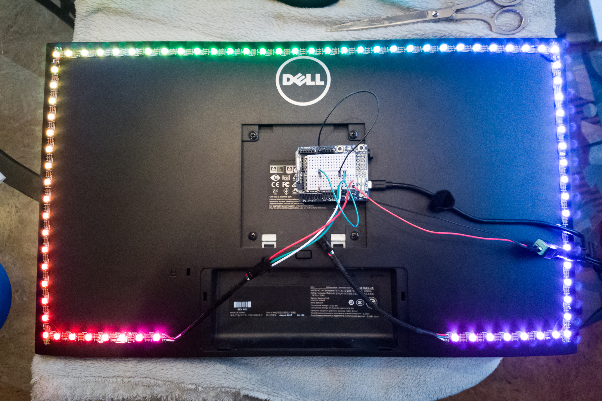
Before soldering, make absolutely sure the data direction is correct. For my setup the data direction runs counter-clockwise when viewing from the front, which is the same direction the default Prismatik config goes. Here’s a trick for soldering: only the data wire has to be in-line! Both the power and ground wires can run from anywhere on the strip. In fact: if you’re running a long strip, it’s best to apply power to various points along the strip to prevent voltage drops. To avoid overlaps, I ran the power wire to the next row over and the ground wire from the previous row on the source strip.
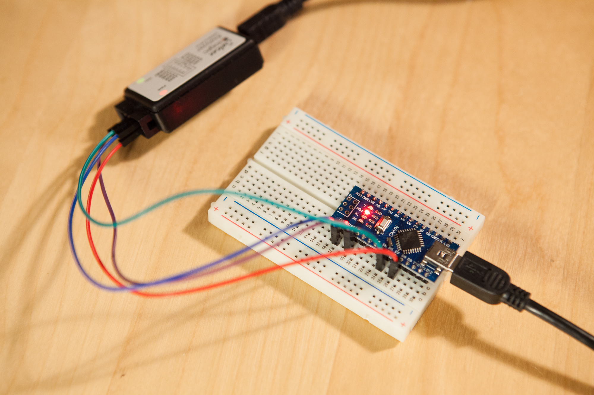
 After each segment was soldered I tested the setup using an Uno and a FastLED test sketch to make sure the connections were solid. In my research I also discovered that the 3-pin JST connectors that are sold with all of these strips are only rated to handle a maximum of 3 amps (!!!). For a 5m strip that can use up to 18 amps at full brightness, that’s a scary thought. For this small 80 pixel setup, the max load it will ever see is 5 amps (80 pixels * 3 diodes per pixel * 20 mA), and after calibration it’s likely to never be close to that. Still, it’s better to err on the safe side so I put a second JST connector on the end of strip for power. Make sure you are using a power supply that can handle the load, you cannot run these LEDs at full power using the Arduino or USB power. Don’t break things, use an adequate 5V power supply. I’m using this 10A power supply (affiliate link)
, which is a little overkill for this project.
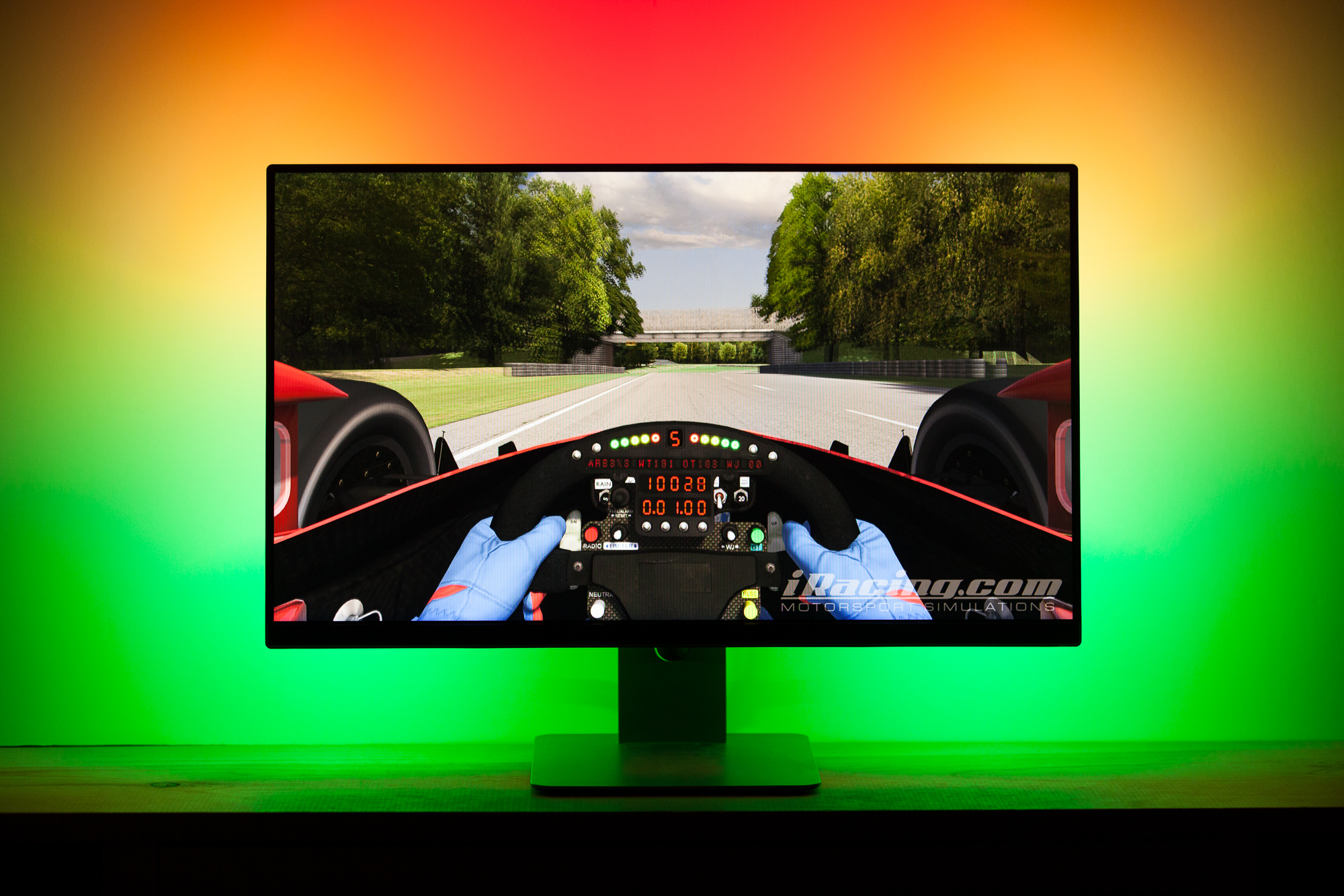
Once everything has been cut and soldered, it’s time to attach the LEDs to the monitor. I used some 10mm 3M tape with 300LSE acrylic adhesive which holds great and shouldn’t be too difficult to remove if I ever need to replace the LEDs.
And just like that, we’re up and running!

22 Comments
Mason · April 16, 2017 at 8:45 am
Can you explain please how did you connect the less to the Arduino ?
and i see that you have a transistor in the bread board , is that necessary or optional ?
Dave · April 17, 2017 at 4:16 pm
The LED strand is composed of WS2812B addressable LEDs. The “Data In” line of the LED strip is connected through a 470 Ω resistor to one of the Arduino’s I/O pins. The resistor isn’t strictly necessary, but it helps prevent the strip from drawing too much current through the pin.
Pablo · June 15, 2017 at 9:24 am
Hi, I have the same configuration as you. A 24″ screen with 80 LEDs. I have bought a 5V 4 Amps power supply. Do you think it will run correctly?
Thanks in advance
Dave · June 15, 2017 at 4:32 pm
No. You’ll have to turn down the brightness to avoid overloading the supply.
Pablo · June 16, 2017 at 5:27 am
Ok, I so I need yo buy at least 5V 6A?
Pablo · June 16, 2017 at 6:15 am
Ok, so I need to buy at least a 5V 6A power supply?
Dave · June 16, 2017 at 3:54 pm
Budget ~60 mA minimum per LED. So a 6A supply should be fine.
hackmonker · November 2, 2018 at 11:45 am
so you connected the uno with the pc through usb right? i mean it receives data from pc through usb right?
Dave · November 2, 2018 at 12:42 pm
Yes.
Jean · March 14, 2019 at 9:03 am
Hi Dave,
thank you so much for this great tutorial!
Do you know whether the 3 amp maximum also applies to 4-pin JST connectors? (I’m using WS2801.)
In my setup, there will only be 1.5 meters worth of strip. I’m still planning to supply power from both ends. I’m a little confused though because there are additional cables for power and ground attached to the beginning of the strip and the power cable is a little thicker than the others. Ideally, I would like to get along exclusively with the two JST connectors.
Dave · March 14, 2019 at 5:09 pm
Hey there!
I don’t know for sure, but I’d imagine that it does. You should look up the datasheet if you want to know definitively.
The extra power cables are there for exactly that reason – the JST connection is not rated for the power requirements of the full strip. You can tape those wires off if you’re not going to use them, just so long as you’re within the power limits of the JST connectors.
Jean · March 14, 2019 at 6:15 pm
Hm, that’s what I was assuming. On the other hand, the strip uses 10 watts per meter, or two 2 amps. I checked the datasheet and the rating is indeed 3 amps (unless there are versions with differing cables or something). This leads me to believe that the JST connector would be enough for a single strip and that using connectors at both ends would be enough to power 1.5 meters … But I might well be wrong. Perhaps it’s because the strips are sold in sizes up to five meters?
On a kind of related note: Does it make sense to add a 3 amps fuse to the power output to make sure the connections won’t be overloaded?
Thanks for taking the time to answer!
Dave · March 14, 2019 at 7:25 pm
Yeah the addressable LED strips are usually sold in varying lengths and with varying densities (30/m, 60/m, etc.) so it’s not surprising they would use the same connector setup for every one.
You can add a fuse if you’d like, it won’t hurt anything (assuming you spec it correctly).
Simone · October 17, 2019 at 6:54 am
Hi!very nice build guide, thank you!
It is possible to use ambilight with a double screen setup? (on same pc)
Thank you very much!
Simone
Dave · October 17, 2019 at 5:08 pm
I believe so, but you’d have to test it yourself. Last I checked the software doesn’t support multiple devices, so you would need to use one big LED strip across both monitors and tie it into one Arduino. Then arrange the capture zones yourself across both monitors.
Bob · October 23, 2019 at 10:50 am
Hello.
What are the multi coloured wires called which you used to connect the different LED strips together? I can’t find them anywhere because I don’t know what they’re called haha.
Thanks
Dave · October 23, 2019 at 12:06 pm
Between the different strips? That’s just run-of-the-mill 22 AWG stranded wire, cut to length and then soldered.
The wires with connectors that go between the microcontroller and the LED strip are pre-assembled 3-pin JST connectors with leads. I have a link to the ones I used on the ambilight project page, here: https://www.partsnotincluded.com/projects/ambilight/.
Frederic Abraham · December 18, 2019 at 9:25 pm
I’m not sure if you did this but I couldn’t find it in the post.
I ran into a lot of problems when I didn’t connect the ground of the external power supply and the ground of the arduino.
The LED’s would go crazy and eventually die.
Afterward, I read here https://github.com/FastLED/FastLED/wiki/Power-notes that it is important to do so and that fixed the issue.
A second note I’d like to make is that due to FastLEDs “temporal dithering” you don’t have to slam full brightness on the LED’S to get the same light level output.
As a result, you don’t have to get a super beefy power supply if half the brightness is enough for you. Of cause, if you go this way you should use a multimeter to figure out the max amperage the strip is using with your specific brightness need.
https://github.com/FastLED/FastLED/wiki/FastLED-Temporal-Dithering
Thanks for sharing your experience. I wished I found it before i killed a LED 😀
Dave · December 19, 2019 at 8:04 pm
Hey there! You’re absolutely right, it’s critical that the ground connections between the Arduino and the power supply are linked. I thought I had mentioned that in the PCB post, but it looks like I just included it in the schematic. I’ll have to revise the post and emphasize how important it is.
I’m not sure about your first point re: the temporal dithering. The only way to get full brightness output is to run the LEDs at full brightness; any dithering will reduce the total output. The purpose of dithering isn’t to get more brightness, it’s to make changes in the output level smoother when you have a smaller range of output values.
The temporal dithering is a great feature of the library but it doesn’t work well with this project since the
showfunction is only called after a full frame of LED data is received. The data is almost certainly just rescaled without any dithering going on. If you can get an adequate power supply to handle all of the LEDs at full brightness, it’s much better to do the brightness limiting on the PC side where the data is generated.Frederic Abraham · December 20, 2019 at 10:32 am
About this full brightness: It sure ist true that you only get full brightness if you put the brightness level at max. It’s just that at least for my LEDs and my setup that’s way too bright to be comfortable with and if you don’t have a 10 amps power supply maybe less is also ok. But in the end, you can just modify the brightness in Prismatik. It’s just that with my 55″ monitor and the led strip I got 165 LEDs on the back and getting a 20 Bucks power supply kinda defeats the purpose of low budget ambient light.
Anyways I’d like to make a small request. I never really learned about electrics and stuff and don’t understand why connecting the grounds is important.
Would you be so kind as to explain why or point me into a direction where I can read about it?
Dave · December 20, 2019 at 2:09 pm
Connecting the grounds is important because voltage is relative, not absolute. With two power supplies you have two different grounds with two different ground (reference) levels, so what is +5V to one supply may only be seen as +3V from the other.
By connecting the grounds, you ensure that both supplies see the same reference level and voltages between the two supplies are as expected.
Earl Jackson · January 13, 2021 at 1:14 pm
Im trying to see if there is anyway to connect the LED strip that I currently have on my im rig(cheap china ones with a 10v power supply you plug into the wall.) Ive looked up all kinds of things but nothing really says if this is possible. The lights run into a box, which the power supply plugs into. Any ideas how I would make it work?