A few months ago I was attempting to reformat my laptop as a dual-boot machine with both Ubuntu and Windows 10 and I was having issues getting the boot manager to properly detect both operating systems. Shortly after changing a setting in the BIOS related to SATA operation, the laptop suddenly stopped working after rebooting. Powering it on resulted only in a pure black screen where after approximately fifteen seconds it flashed “Lenovo Misto Ontario”, and then nothing. It was true and thoroughly “bricked”.
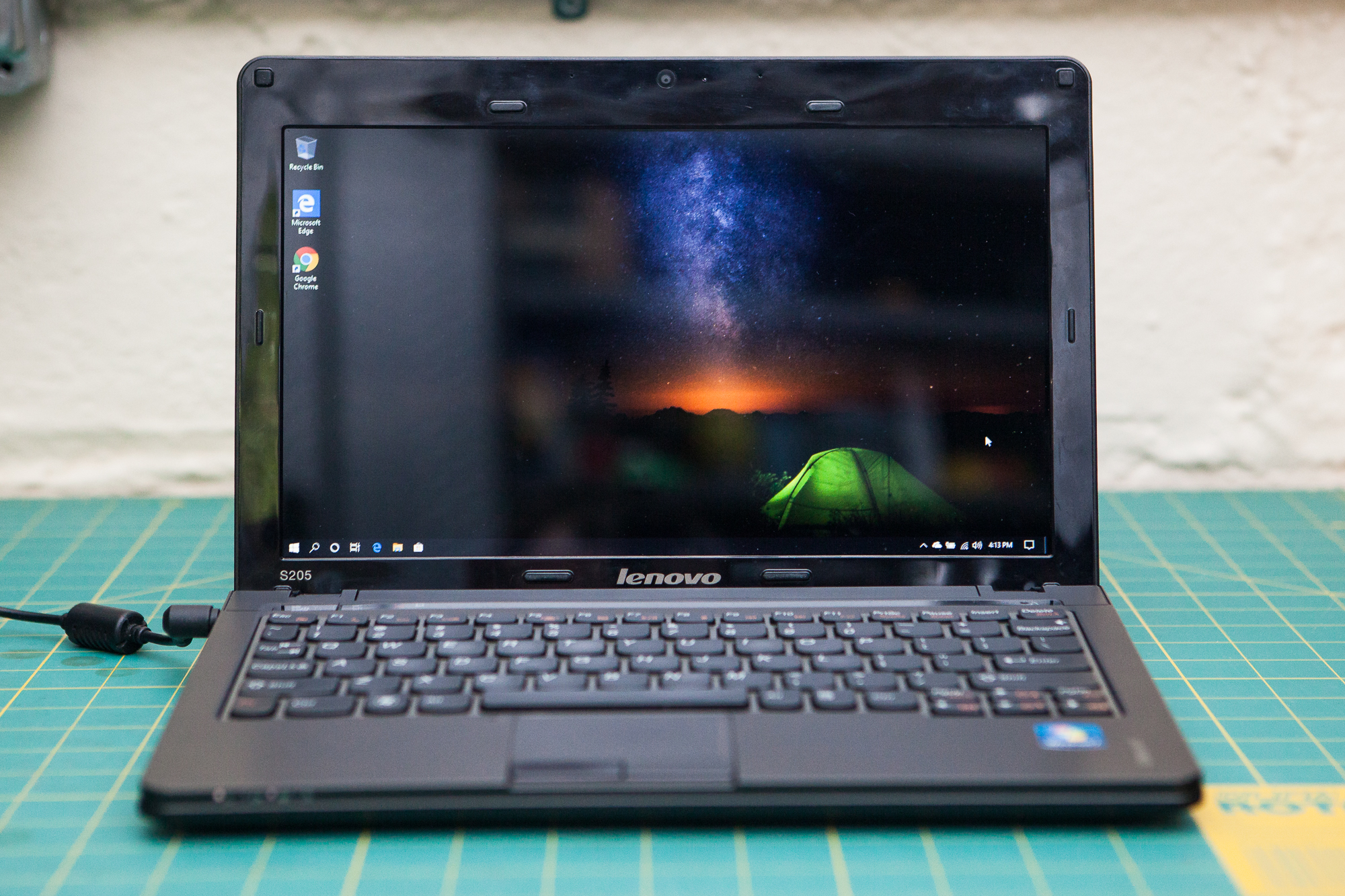
I tried everything I knew to fix it, including pulling the CMOS battery, reformatting the hard drive, and trying to ‘auto-flash’ the BIOS from a USB drive – nothing worked. I’ve had this little Lenovo S205 netbook for a few years and although it’s gotten slower it’s always served me well. And since it was working perfectly fine up until it er, wasn’t… it seemed like a waste to just throw it out without trying my best to fix it.
I’m happy to say that I succeeded. The solution was to reflash the BIOS chip with a replacement BIOS I found online, using an open source program called ‘flashrom’ and an Arduino acting as an SPI flash programmer. Here’s how I fixed it.
Meet the Target
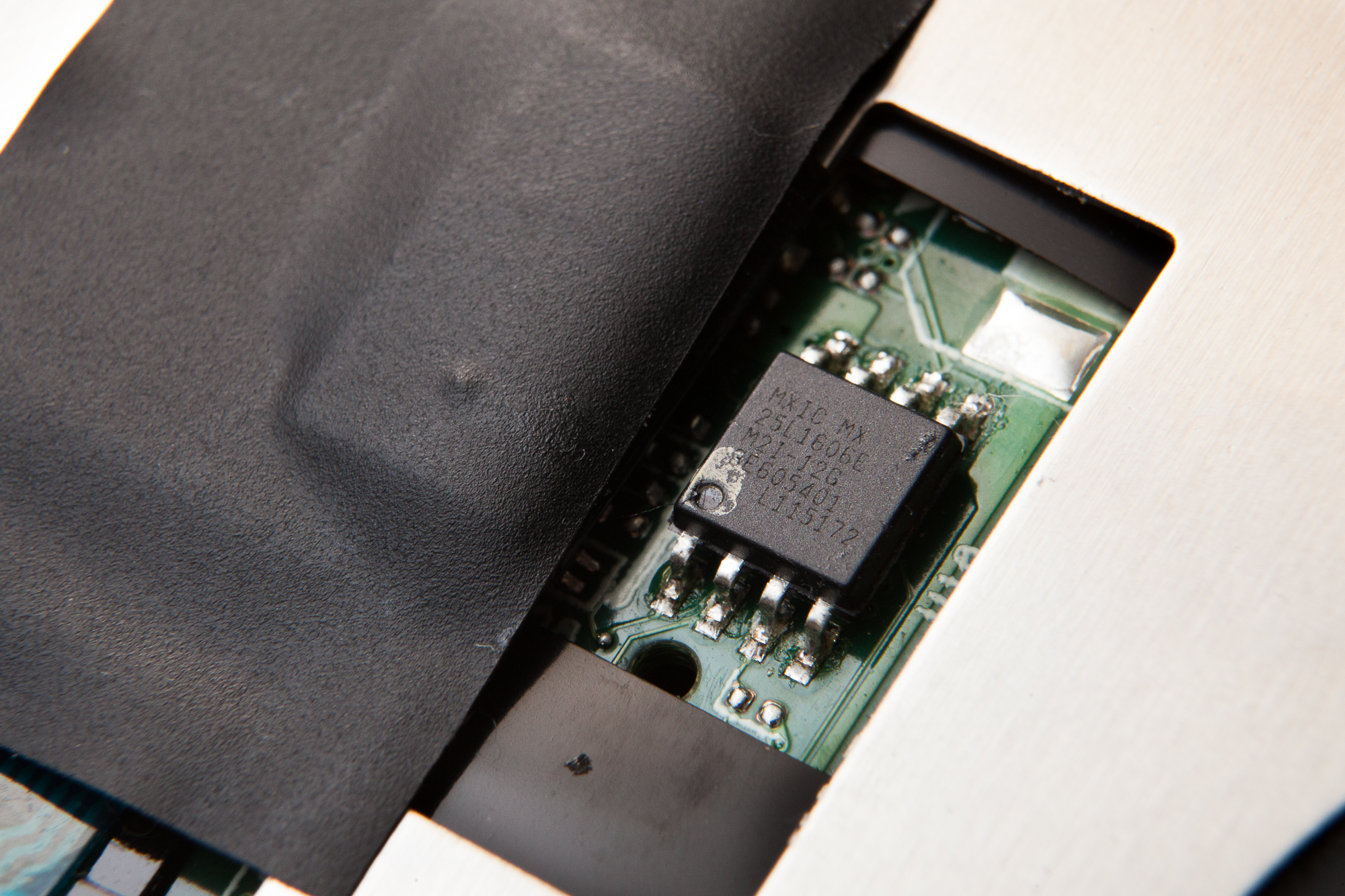
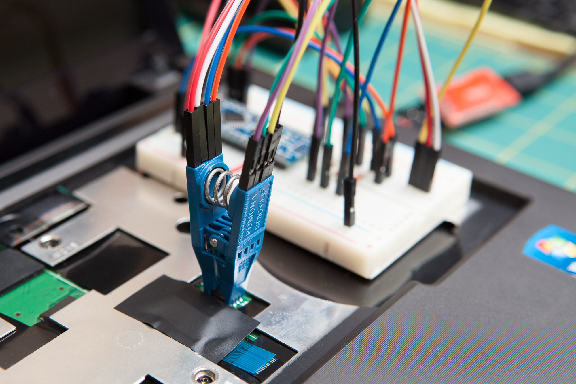
The target for this fix is a small flash memory chip on the laptop’s mainboard that contains the instructions which make up the computer’s BIOS. The chip in question is located directly underneath the laptop’s keyboard and accessible by moving a small plastic flap out of the way (held in place with electrical tape in the above photo). The chip is stamped with the following information:
MXIC MX
25L1606E
M2I-12G
3E605401
L115172
This identifies the chip as a Macronix MX25L1606E, M2I-12G variant in an 8-SOP package. It uses a serial peripheral interface (SPI) for communication and has a capacity of 16,777,216 bits (2,097,152 bytes, or 2 mebibytes (MiB) for short). On board are all of the instructions for the computer’s BIOS.
Getting a “Clean” BIOS ROM
The theory behind this fix is that the existing BIOS on the laptop’s board is somehow corrupted, and can be fixed by replacing it with a non-corrupted version. So before going any further, I needed to find a “clean” version of the laptop’s BIOS to flash to the chip.
Thankfully the support documentation and downloads are still available on Lenovo’s website, including a BIOS update that is dated August 16th, 2011. This comes as a Windows executable labeled 4BCN24WW.exe, and is intended to be run in a Windows environment on the S205 laptop. The program will automatically check that it’s on the proper machine and then rewrite the BIOS while the PC is still running. Since the laptop is “bricked” I can’t use that process, but I can extract the BIOS file from the executable.
On my Windows 10 desktop, I ran the executable where it promptly threw an error that I needed to “Please connect the battery” and then exited. Before it errored however, it extracted its contents to the following folder in preparation to run:
%USERPROFILE%\AppData\Local\Temp\WinFlash
At the top of this folder is the file BIOS1.WPH. This is the BIOS ROM that is going to be flashed to the laptop.
Building flashrom
The software I used to flash the BIOS memory is called flashrom. In the developers’ own words:
flashrom is a utility for identifying, reading, writing, verifying and erasing flash chips. It is designed to flash BIOS/EFI/coreboot/firmware/optionROM images on mainboards, network/graphics/storage controller cards, and various other programmer devices.
Rather than downloading someone else’s pre-built binary, I built the software from source using the latest stable release, 1.0.1. Since my normal operating system is Windows 10, I used a Linux “live USB” of Ubuntu 19.04 for this process (18.04 LTS seems to have a bug with group management when booting from a live CD which prevents talking to USB devices).
Preparing the Environment
Before anything else, I needed to change the package repository sources to pull from ‘universe’ in order to fetch some of the necessary packages including libftdi and gcc-avr. The ‘universe’ repository is enabled by default for installations, but not when using a ‘live-USB’. After adding the ‘universe’ repository I also needed to update the package list:
$ sudo apt-add-repository universe
$ sudo apt update
Once that finished, the first order of business was to install git so that I could clone the repository. Then I cloned the latest stable release from the flashrom repository and changed directories:
$ sudo apt install git
$ git clone --branch v1.0.1 https://github.com/flashrom/flashrom.git
$ cd flashrom
Installing Dependencies
Before building flashrom from source, I needed to install all of the dependencies. According to the README for version 1.0.1, this includes:
- pciutils+libpci (if you want support for mainboard or PCI device flashing)
- libusb (if you want FT2232, Dediprog or USB-Blaster support)
- libftdi (if you want FT2232 or USB-Blaster support)
On Ubuntu 19.04, here are the packages I used:
In one easy install statement:
$ sudo apt install libpci-dev libftdi-dev libusb-0.1-4 libusb-1.0-0-dev
Compiling
After the dependencies were installed, I compiled flashrom from source and then installed it:
$ make
$ sudo make install
Check that it’s installed by typing ‘flashrom’ into the terminal. You should see an output similar to this:
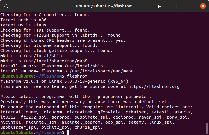
With flashrom installed and ready to go, I then moved on to assembling the hardware for the programmer.
Making the Programmer
Normally you would reflash a computer’s BIOS using the computer itself, but since the laptop is bricked I need to do it “by hand” so-to-speak. This means connecting a device that speaks SPI directly to the pins on the flash memory chip that holds the code for the BIOS. This programmer then connects via USB to flashrom, which commands it how to move data to and from the memory chip.
Gathering Hardware
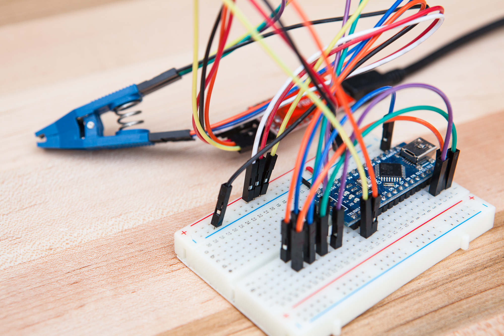
The completed DIY programmer, made with an Arduino Nano, FTDI FT232H, and Pomona SOIC-8 test clip.
(Be aware that some of these links go to Amazon and help fund this and other projects. Thank you for your support!)
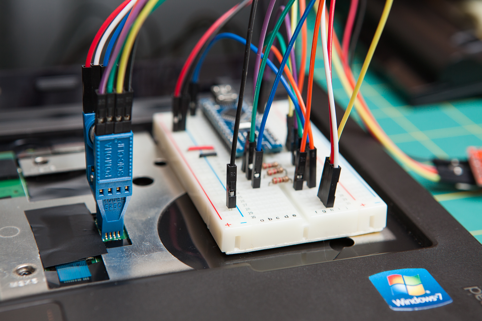
For my programmer I used an FTDI FT232RL board module in combination with an Arduino Nano, connected together using male to female DuPont jumpers and a solderless breadboard.
The Arduino is the brains of the operation. The ATmega328P chip at the heart of the Nano runs some custom firmware, built by the flashrom community, that translates the serial instructions sent by the host PC into SPI flash instructions for writing to the memory chip. I’m using a Nano instead of an Uno (which also uses the 328P) just because it’s easier to breadboard.
The FTDI board functions as a USB to UART (serial) adapter and provides a 3.3V power source to run the Arduino. This is necessary because the flash memory chip on the laptop normally runs at 3.3V and is not 5V tolerant. By using the FTDI as a pass-through, the Nano runs at 3.3V and has 3.3V outputs that play nicely with the flash memory.
To connect to the flash chip itself I’m using a Pomona 5250 SOIC-8 test clip. This is a spring-loaded adapter that connects directly to the fingers on the chip and makes solid connections without any soldering.
Alternatives
Although the FTDI / Arduino combination worked for me, I only chose it because I already had those parts on hand. flashrom supports a whole host of programmers, including the FTDI FT232H and the Dangerous Prototypes Bus Pirate. If I didn’t have all of the other hardware on hand, I would have just picked up an FT232H breakout and been done with it.
It also would have also been possible to use a level shifter or series of voltage dividers in place of the FTDI connection. I went with the FTDI over a series of voltage dividers because I wanted to attempt to program the chip while it was on the board, and the SPI current using voltage dividers would have been too low (I didn’t have any digital buffers on hand).
Since the serprog protocol is open source it also would have been possible for me to write a custom implementation of the protocol for a 3.3V microcontroller I already have on hand, such as the Teensy LC. But this wasn’t a project to learn about flashrom, this was a project to fix my computer, so I took the quick and easy way out.
Fun fact: while I was writing this post, I realized that I could have also just used a spare Raspberry Pi with its SPI header which runs at 3.3V – avoiding the Arduino, FTDI board, and the Ubuntu live CD. Live and learn…
Flashing the Arduino Firmware
The first step in assembling this DIY 3.3V SPI flash programmer (say that five times fast…) is to upload the custom firmware that works with flashrom. I’m using frser-duino, which is a serprog-based firmware. These instructions are loosely based on this page from the flashrom wiki, which unfortunately has a couple of incorrect instructions and is missing a few crucial steps.
Building from Source
To start, I needed to clone the frser-duino repository to my machine, and then change directories:
$ git clone --recursive https://github.com/urjaman/frser-duino.git
$ cd frser-duino
The “–recursive” flag is necessary on the clone command so that the serprog library submodule is cloned with the rest of the repository.
Before compiling the firmware, I needed a copy of the avr-gcc toolchain for compiling the firmware. The toolchain consists of three packages: the GNU C compiler, utilities for manipulating AVR binaries, and the AVR C library:
As before, install in one easy statement:
$ sudo apt install gcc-avr binutils-avr avr-libc
With the AVR toolchain installed, I then built the firmware using the included makefile with no modifications:
$ make u2
Since the ATmega328P microcontroller at the heart of the Arduino Uno does not contain a USB controller, the genuine development boards use an ATmega16U2 to handle the USB to UART conversion (hence the ‘u2’ in the make command). The developers who wrote frser-serprog don’t think very highly of the U2 firmware, so building for the ‘u2’ target will set the baud rate to 115200 and add a 10 us delay when sending data.
I’m using a knockoff Arduino Nano that doesn’t even have a 16U2 (it uses the sketchier CH340G, while the genuine boards use the FT232RL chip), and in fact since I’m using the FTDI board to connect directly to the Arduino’s UART, the onboard USB to UART adapter doesn’t matter in the least. But I’m also pushing the 328P chip slightly outside of its rated clock speed envelope at 3.3V, so I figure the slower baud rate and the slight delay will make it perform more reliably.
Note that I specifically did not change the F_CPU value in the makefile as suggested in the flashrom documentation in order to accommodate the 3.3V supply. Changing the F_CPU value doesn’t change the clock speed – that is set by the fuse bits. Changing the F_CPU value in the makefile will only throw off the calculations for the UART’s baud rate and cause flashrom to report the device as out of sync.
Flashing via USB
With the compiled firmware in hand, the next step is to flash the frser-duino firmware to the Arduino via USB. It’s important that the FTDI board is not connected yet, otherwise the 5V power from the Arduino will damage it.
Before anything else, I needed a copy of avrdude – the program used for flashing AVR chips:
$ sudo apt install avrdude
Next I needed to add the current Linux user to the “dialout” group so that I had permission to talk to the USB device:
$ sudo adduser $USER dialout
$ newgrp dialout
With permission to talk to USB devices, I then needed to check that I’m talking to the correct USB device. A genuine Arduino using a 16U2 chip and supporting more advanced serial options will appear as a ttyACM device. I’m using a knockoff Nano with a CH340G USB to UART chip, which instead shows up as a ttyUSB device. If there are no other devices present, the Arduino will be listed as device ‘0’ – either ttyACM0 (genuine boards) or ttyUSB0 (knockoffs). This number is easy enough to check – with the Arduino disconnected, listing information about the device will report an error:
$ ls -l /dev/ttyUSB0
ls: cannot access '/dev/ttyUSB0': No such file or directory
While after connecting the Arduino, the same command will report information about it:
$ ls -l /dev/ttyUSB0
crw-rw---- 1 root dialout 188, 0 May 23 09:21 /dev/ttyUSB0
Since the makefile assumes the Arduino is genuine and going to show up as ttyACM0, it needs to be modified to point to /dev/ttyUSB0 instead for my knockoff. Finally, I used the makefile and avrdude to automatically upload the firmware:
$ make flash-u2
Flashing the Arduino over USB uses the bootloader and will not break the board’s “Arduino-ness” – meaning it’s still possible to reprogram it through the Arduino IDE after this is all done.
Testing the Arduino
One last step before it’s time to start connecting things up. With the Arduino still connected via USB, I can test the communication between the programmer and the flashrom software:
$ flashrom -p serprog:dev=/dev/ttyUSB0:115200
If everything is working properly, the Arduino should happily report back something similar to this:
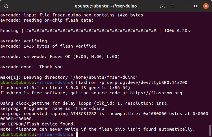
The key line is “Programmer name is ‘frser-duino'”, which identifies the programmer and shows that flashrom and the programmer are in sync. The error about “no EEPROM/flash device found” is perfectly fine, because I haven’t connected the flash chip yet!
Connecting the Hardware
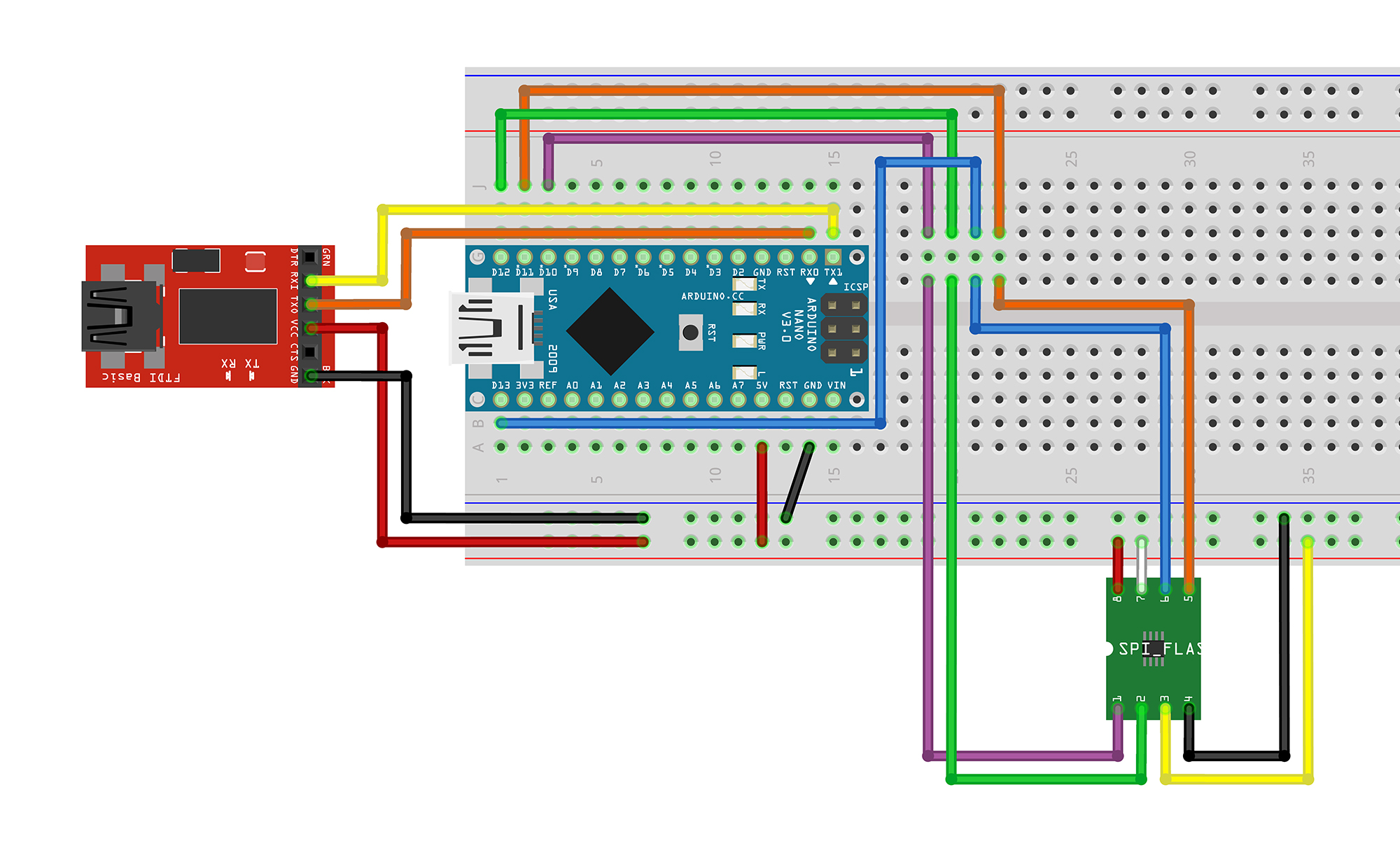
Breadboard connections for the flashrom programmer
After the firmware had been successfully installed on the Arduino and the USB cable disconnected, the next step is to hook up the FTDI board to get 3.3V outputs, and then finally to connect the Arduino’s outputs to the programmer clip.
FTDI to Arduino
The following connections need to be made from the FTDI to the Arduino:
| Function | FTDI Pin | Arduino Pin | Wire Color |
|---|---|---|---|
| Serial In | RX | TX1 | Yellow |
| Serial Out | TX | RX0 | Orange |
| Power | VCC | 5V | Red |
| Ground | GND | GND | Black |
Before proceeding, it’s very important that the voltage jumper on the FTDI board is set to “3.3V”. If it’s set to “5V” the flash chip will be fried and this will all be for naught.
Most of the connections are straight-forward: TX to RX, RX to TX, and GND to GND. The odd man out is the power connection: the 3.3V “VCC” connection from the FTDI board goes to the Arduino’s “5V” pin, which is a little confusing. This is because the pin marked “5V” is connected to the output of the Arduino’s 5V regulator, and is a direct connection to the voltage going into the microcontroller. This is in contrast to the “VIN” pin, going into both voltage regulators,and the “3.3V” pin, coming out of the 3.3V voltage regulator.
Once these connections are made, it’s very important to not connect to the Arduino using USB until the FTDI board has been disconnected. Otherwise the Arduino will back-feed the FTDI board with 5V and fry it. The USB connection should be to the FTDI board only.
After these connections are made, it’s useful to re-run the connection test above to verify that the FTDI board is communicating properly with flashrom. The result should be the same as with the Arduino board – properly identifying the programmer name and only erroring because no flash chip is connected.
Arduino to Flash Chip
With the FTDI and Arduino connected and communicating properly, the next step is to wire to the flash chip itself via the Pomona test clip:
| Function | Arduino Pin | Flash Chip Pin | Wire Color |
|---|---|---|---|
| Chip Select | D10 (SS) | CS | Purple |
| Serial In | D12 (MISO) | SO | Green |
| Write Protect | 5V (3.3V level) | WP# | Yellow |
| Ground | GND | GND | Black |
| Serial Out | D11 (MOSI) | SI | Orange |
| Clock | D13 (CLK) | SCLK | Blue |
| Hold | 5V (3.3V level) | HOLD# | White |
| Power | 5V (3.3V level) | VCC | Red |
The SPI connections are all straight-forward using the hardware SPI pins on the Arduino board. The flash chip also has two pins for “write protect” (#3) and “hold” (#7). Both of these are active low, so they need to be held at a logical high to allow writes and prevent the chip from stalling out.
I know the power connections in the table are a little confusing. These are all connected to the “5V” pin, which if you remember from above is actually running at 3.3V. To reiterate: these connections should not be tied to a 5V source, just the 5v pin, which is not actually at 5V, but rather 3.3V. Cool? Cool.
Testing Communication
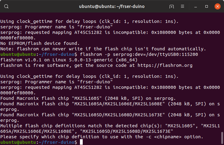
So that I wasn’t flying blind by trying this on the laptop for my first attempt, I ordered a pair of similar Macronix flash chips from DigiKey to experiment with before I tried the real thing. I attached the Pomona clip to the bare chip and then attempted the same flashrom programmer ‘test’ command as before. This time the terminal reported back that it found a Macronix flash chip, and asked me to select the chip definition with the “-c” option.
To start, I attempted a read:
$ flashrom -p serprog:dev=/dev/ttyUSB0:115200 -c MX25L1605A/MX25L1606E/MX25L1608E --read testread.hex
This reads from the flash chip and dumps the output into the testread.hex file. On the blank chip this took about two minutes to run and, predictably, the resulting hex file was completely empty (all ‘0xFF’). This doesn’t mean much, so I decided to step it up by storing and then retrieving some actual data.
I needed some sort of file that’s under 2 mebibytes, non-repeating, and easy to check for errors at a glance. Cue Project Gutenberg’s repository of free public domain e-books! The most downloaded book as of this post is Jane Austen’s Pride and Prejudice, conveniently available in plain text at a cool 707 kB.
flashrom only works with files that are the exact size of the destination chip, so before this was written to the flash chip it needed to be resized:
$ truncate -s 2097152 prideandprejudice.txt
Then the e-book was written to the chip with this command:
$ flashrom -p serprog:dev=/dev/ttyUSB0:115200 -c MX25L1605A/MX25L1606E/MX25L1608E --write prideandprejudice.txt
This took about 15 minutes to complete, during which time flashrom reads the existing contents on the chip, erases and writes any differing bytes, and then verifies that the file was written to the chip successfully.
Once the file was successfully written, it was time to read it back and test that everything is okay:
$ flashrom -p serprog:dev=/dev/ttyUSB0:115200 -c MX25L1605A/MX25L1606E/MX25L1608E --read prideandprejudice_read.txt
After flashrom finished saving the chip’s contents to a file, I opened it in a hex editor for a cursory check:
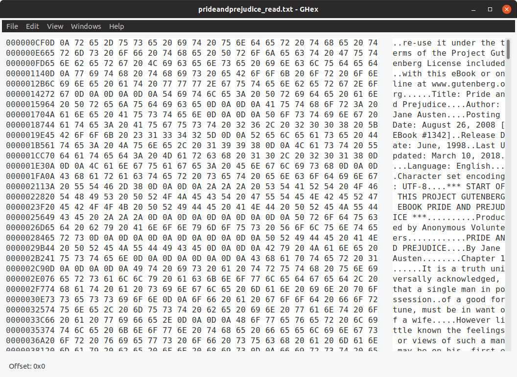
Success! At a glance, at least. For a more thorough check, I then compared the ‘read’ version with the original and checked for any discrepancies:
$ cmp -l -b prideandprejudice.txt prideandprejudice_read.txt
This command printed nothing to the terminal, showing that both files are byte-for-byte identical.
Flashing the Laptop In Situ
Enough testing. The programmer seemed to be working, so it was time to take out the laptop and try flashing the real deal.
After taking out the battery and removing the three screws beneath it, the laptop’s keyboard can be pried up and disconnected. This exposes a small plastic flap near the center of the laptop, under which the MXC flash chip lies waiting.
Modifying Connections
The laptop is a different environment compared to a standalone circuit, so it was time to re-evaluate and change up the connections a bit.
First, the power. The chip runs at 3.3V and when I was programming my standalone chip for testing I powered it from the regulator on the FTDI board. I’m assuming that the FTDI’s regulator doesn’t have enough amperage to power the other connected components on the laptop board, so I disconnected the power lead and powered the laptop from its wall charger instead.
Second, from measuring the connections on the laptop it appears that both the ‘hold’ and ‘write-protect’ pins which need to be held ‘high’ for the chip to function already have existing pull-ups (10 kΩ for WP#, 4.6 kΩ for HOLD#). Since these were already pulled-up I didn’t need to connect them to VCC. For simplicity’s sake I left the wires connected to the clip but floating on the breadboard.
To protect against possibly shorting one of the digital connections on the laptop’s motherboard, I also put 220 Ohm resistors in series for all of the logical connections (CS, MOSI, MISO, CLK). This shouldn’t have any significant effect on the result, since the flash chip’s inputs are high impedance anyways.
Flashing
Hold your breath, because here we go…
After adding in the resistors and disconnecting the VCC / WP / Hold connections, it was time to rumble. I plugged in the laptop’s wall charger to provide 3.3V to the chip, and then plugged the FTDI board’s USB cable into my ‘flashing’ machine..
Unfortunately, trying to talk to the programmer resulted in either an “cannot synchronize protocol” error or a “no flash chip connected” message with no further elaboration. Ugh.
I was quite determined to get this working without having to desolder the BIOS chip, so I tried everything I could think of to get the programmer to cooperate:
- Double-checking all connections
- Connecting WP and Hold to 3.3V directly
- Removing the 220 Ω resistors on the digital lines
- Powering the Arduino from the laptop 3.3V
- Powering the laptop from the FTDI’s 3.3V
The only obvious thing I didn’t try was rewriting the Arduino’s fuses to function with the 8 MHz internal oscillator instead of the slightly overclocked 16 MHz external crystal. Although since the programmer worked perfectly fine on the practice chip I’m not sure that would have made a difference.
Unfortunately I don’t have a quality scope to try to inspect the SPI lines, although I’m not sure I would have been able to do anything even if I did find the problem. Time for plan B.
Flashing the Laptop After Desoldering
During all of my testing, the programmer seemed to work fine so long as the flash chip was part of the programmer’s own isolated circuit. So that’s what I decided to do – isolate the flash chip by removing it from the laptop’s mainboard.
Desoldering
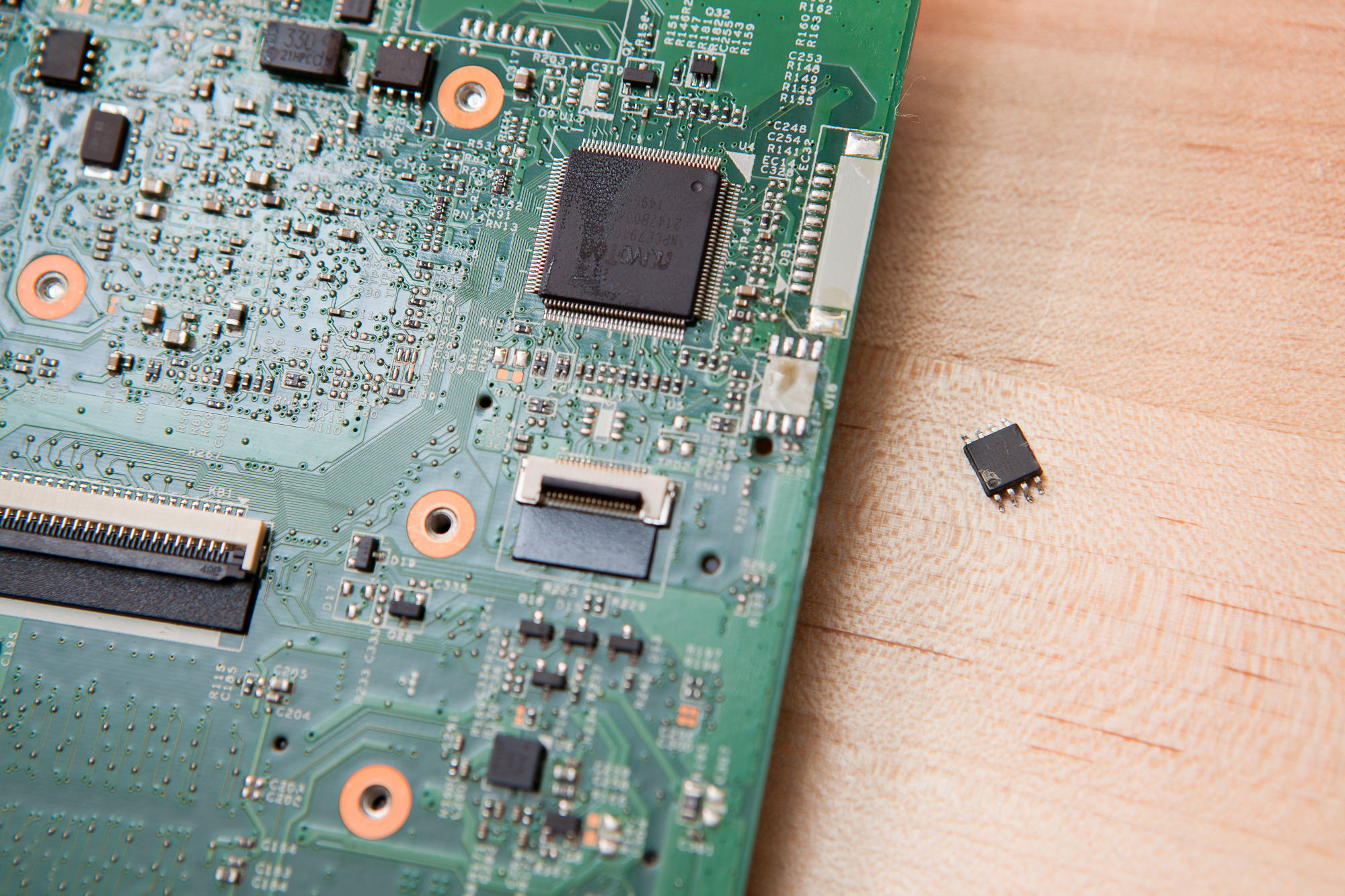
The BIOS flash chip, desoldered from the laptop’s mainboard and ready for flashing.
The BIOS chip’s position just below the keyboard is quite convenient for accessing with a programming clip, but not so convenient if you need to desolder it. At a minimum, using a hot air rework station in that position would melt the plastic shielding on top of the motherboard. If I wasn’t careful I might also damage the laptop’s casing or screen, so I decided to disassemble the machine further.
After pulling off the bottom cover, getting to the chip requires removing the hard drive and undoing the two ribbon cables going to the I/O daughterboard, the cable to the front speakers, and the two remaining connections underneath the keyboard. After removing the four remaining screws holding it down, the mainboard flips over along the screen hinge axis revealing the CMOS battery and the BIOS flash memory chip underneath the plastic cover.
To remove the chip, I used a cheap hot air rework station and a pair of tweezers. After a minute of warming it the solder connections loosened up and the chip lifted free from the board. I’m still a rank amateur when it comes to hot air soldering, so I was glad that the chip is at the edge of the board and away from most of the minuscule components that could otherwise walk out of place.
Flashing… For Real This Time
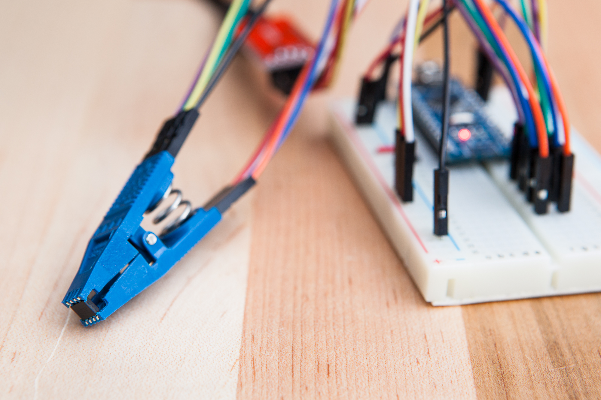
One of the practice chips in the Pomona test clip, ready for flashing.
BIOS flashing attempt #2, this time with everything under my control. No mystery circuits, pre-existing pull-ups and dual power supplies – just the programmer and the chip.
Thankfully, the chip showed up immediately and functioned just as its siblings had – identifying itself as a Macronix flash chip with 2048 KiB of memory. The virtues of practice are evident: after spending so much time preparing myself for programming “the real deal” with my practice chip, this part was a breeze.
First, I saved a copy of the BIOS that was on the chip:
$ flashrom -p serprog:dev=/dev/ttyUSB0:115200 -c MX25L1605A/MX25L1606E/MX25L1608E --read brickedbios.wph
This took about two minutes to complete. Once it was done, I compared the ‘clean’ BIOS I pulled from the web to the one I had just pulled from the flash chip:
$ cmp -l BIOS1.WPH brickedbios.wph
This printed a few hundred lines of byte mismatches, which is a good sign. For one, only a few hundred mismatches means that both BIOS files are relatively similar. In other words, it means that it’s likely that the ‘clean’ BIOS I found will work on the machine. Two, a significant number of byte mismatches means that my theory that the BIOS is corrupted holds water, and that replacing the BIOS may “un-brick” the PC.
With the old BIOS safely saved, it was time to reflash the chip with the clean BIOS:
$ flashrom -p serprog:dev=/dev/ttyUSB0:115200 -c MX25L1605A/MX25L1606E/MX25L1608E --write BIOS1.WPH
This only took about 5 minutes, significantly less time than writing Pride and Prejudice to the fresh chip. This is because flashrom only needed to write the changed bytes rather than the entire file.
After all of the trouble getting the chip to program, it was a relief to see the “flash verified” notification at the end of the write process. Nothing left to do other than to disconnect the programmer, re-solder the chip to the mainboard, and see if the laptop will boot.
We Can Rebuild It
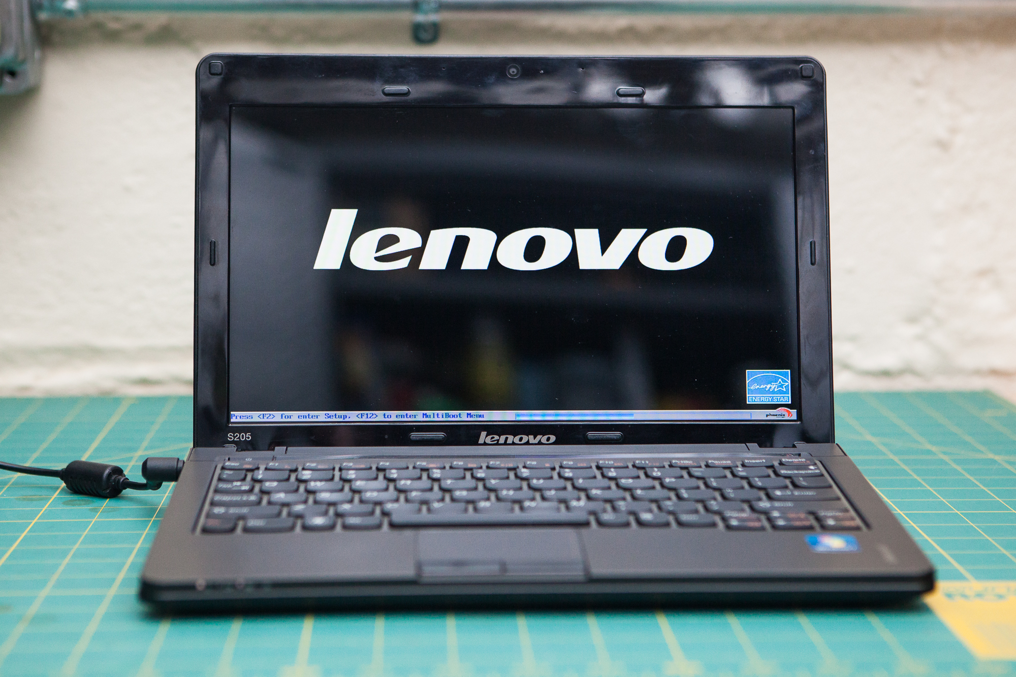
I’ve never been so happy to see a BIOS splash screen
Re-soldering the chip was significantly easier than desoldering it. A little bit of flux and a few seconds on each pin with a handheld iron put it back in place. Then began the slow and deliberate process of re-attaching all of the ribbon cables and screws to re-assemble the laptop back to working order.
Once the machine was back in once piece, I opened up the screen and held my breath. After connecting the wall charger, the laptop immediately sprang to life and greeted me with the “Lenovo” splash screen, followed by an angry message that the CMOS checksum was invalid. Good to see you too!
The only significant change I can see in the BIOS is that the laptop’s serial number is missing. A small price to pay for making the computer work again.
Conclusion
It’s been a little over a week now and the laptop is still happily chugging away, having survived another dozen or so reboots from installing and updating Windows. Hopefully this will last another few months at least, the only x factor is my questionable resoldering skills. I mostly use it for portable electronic experimentation (e.g. playing with those musical floppy drives) so it’s not doing any heavy lifting, but I’m glad that it’s back on its feet. Time to look back on this little adventure with some final thoughts.
Economics
First off, was this an economical fix? No, not really. I had most of the parts on hand already, so I only needed to buy the Pomona test clip – approximately $15 USD. That’s about the same cost as a replacement S205 motherboard from eBay. If I had needed to buy any other parts for the programmer it wouldn’t have been worth it.
I’d estimate that it took more time to do the research, practice, desolder, and then flash the BIOS chip than it would have to swap out the laptop’s mainboard for a replacement. Although having done it once I’m sure it would be much faster to desolder and flash the chip again. Plus I learned some stuff!
Tools
Second, how well did the flashrom/programmer setup work? All-in-all, it seemed to work pretty well. flashrom itself seems fairly robust and easy to use. The ‘practice’ chips I was using were detected automatically and flashed with no issue. The Arduino ‘serprog’ firmware, despite its slow speed, also seemed to work quite well up until I tried to flash in situ (although I can hardly blame the programming for what is likely a hardware fault).
If I had to do it again, I’d probably still use flashrom as my tool of choice. Although I’d likely swap out the FTDI / Arduino programmer for something a little more robust and self-contained.
How the Heck
Last but not least, how is it possible that installing an operating system causes the machine to corrupt its own BIOS? I didn’t believe it when it happened, and none of my tech friends I told the story to believed it either. From searching online it appears that this was a relatively common problem with these Lenovo netbooks. My only guess is that there’s some sort of a hardware bug present in these laptops pertaining to the BIOS chip. But who knows for sure.
All-in-all, this was a fun troubleshooting project and I’m glad I’ve got my laptop back in working order. On to the next!

11 Comments
Tolga · October 26, 2019 at 7:58 pm
Thanks for your article! It helped me a lot!
I was trying to ISP a 3.3V flash chip, but only had a CH341A around and a couple of Arduinos. The CH341A was 5V and 3.3V using resistor dividers didn’t work.
I tried a bunch of other things, including using serprog / frser-duino, but nothing worked. Your following comment brought up an idea:
“The only obvious thing I didn’t try was rewriting the Arduino’s fuses to function with the 8 MHz internal oscillator instead of the slightly overclocked 16 MHz external crystal.”
So, I used an Arduino Uno (original) in order to feed a breadboard ATMega328P with 3.3V and run it at 8MHz (internal). After using the Arduino in order to flash frser-duino on the breadboard ATMega328P, I shorted Reset to GND on the Arduino in order to use it as USB TTL. I then used resistor dividers in order to get RX and TX down to 3.3V for the ATMega328P and all was set.
Everything else I hooked up based on your schematics and the flashrom wiki. At first, it didn’t work. But after I removed VCC, WP and HOLD, everything worked for some reason. As there is no external power, I have no idea, WHY this worked, but it worked.
Well, kinda. The dumps had 1 – 2 bit differences (always somewhere else), but all in all their content looked valid. Drawbacks were: since the ATMega328P was running at 8MHz, I had to lower the baudrate down to 57600, which might be a no-go for reading big ROMs. Didn’t try writing, as it wasn’t stable enough.
This was a full-day project for me, only with partial success. Using a Raspberry Pi, this would’ve been a 20 minute project (unfortunately, I don’t have one). I wonder, if going with an FTDI, instead of the Arduino Uno’s 16u2 would’ve made a difference…
Dave · October 27, 2019 at 3:29 am
I’m glad you found it helpful!
That’s so strange that it worked for you without VCC connected, the chip must have been pulling power from one of the data lines. From what I’ve read the frser-duino devs really think poorly of the 16U2 USB to serial implementation, but at 57600 I don’t imagine it would’ve made much of a difference.
Tolga · October 27, 2019 at 8:58 am
Yeah, it really puzzled me. Either there was something wrong with my wiring or the circuit of the target device had something weird going on.
Either way, I have an FTDI and some oscillators coming my way this week. I have to revisit this. Also, in order to rule out loose connections, I have ordered some SMD clips aswell. My knock-off SOIC8 test clip was difficult to mount and I wonder, if that was the issue.
Tolga · November 6, 2019 at 11:49 am
Alright, got it solved. The key was to examine the dumps. As you said, the chip was probably pulling power from the data lines and thus lead to incostitent dumps: the differences in dumps only existed in “empty” space. “FF”s slowly turned into e.g. “FF FF FE 80 00 00 00 …” and created a slightly different dump everytime. Astonishingly, the part of the EEPROM containing non-empty data was read without errors among all dumps!
The solution was to wire 3.3V to HOLD and leave VCC / WP unconnected. This way, empty space read as “FF”s all the way to the end and I was able to read consistent dumps. Please note, connecting VCC and / or WP resulted in the EEPROM chip not beeing detected at all.
End of story: I erased the EEPROM of the WD MyBook PCB and am now able to use any SATA HDD of any manufacturer. Until now, this was achieved by cutting pin 8 / removing the EEPROM and thus irrecoverably damaging the hardware / voiding your warranty. But using this method, I can flash back the original content for warranty claims.
Couldn’t have done it without your article. Thanks again!
Dave · November 6, 2019 at 11:43 pm
How odd. It definitely sounds like there just wasn’t enough power to hold the data line high and power the chip throughout the empty blocks. Thanks for sharing your solution as well! I’m sure other people with those drives would also love to know how to flash them without damaging the PCB.
Jeff · April 14, 2021 at 1:13 am
Good post. Using a CH41 programmer for a similar problem. It’s painful to decipher what is good data from the orginal BIOS after doing a read of the chip data on a dead system.
Philip L Waters · April 20, 2021 at 5:35 pm
It’s nice to have someone else go through the pain so I can make the decision of time investment on my own. I’ve decided not to!
But like Jane Austen, it can be nice to use the written word escape into someone else’s word for a moment.
Sounds fun… I’ve got one more thing to try before I call this the end of my journey.
Anton · June 11, 2021 at 5:35 am
Great write up, thanks.
I have a similar issue with a corrupt main bios on a T520 laptop that has a Micron/Numonyx/ST flash chip “M25PX64”
When I extract the bios EXE file i get 3 files: $01C9100.FL1 $01C9100.FL2 $01C9110.FL2.
How can you tell which one should I flash into a bios chip? (Using RPi with SPI connection and flashrom)
Thanks!
A
Dave · June 11, 2021 at 6:28 am
Hi Anthon. Unfortunately I don’t know the answer to that.
Daniel KIFAYA · August 28, 2023 at 2:33 am
You could try searching the corrupt bios save file for the computer serial number that was missing in the clean dump you used to unbrick. if located, modify the clean dump by inserting the serial into the exact hex position via overwrite in a hex editor like hexd or something. that works on mac for the same process.
Dave · August 28, 2023 at 12:43 pm
Good points! I did consider searching through the old BIOS file, but quite honestly once I had it up and running I didn’t want to tear it apart again.