I spend a fair amount of time down in my garage working on things, and while I’m doing that I like to listen to music. I set up an old computer that runs Spotify and sends the audio to a pair of bookshelf speakers. This setup works great, but it requires using a keyboard and mouse to control it. Often times my hands will be gloved and coated with something nasty: grease, epoxy resin, paint, you name it. So I wanted to come up with some sort of method to control my music when my hands were unavailable.
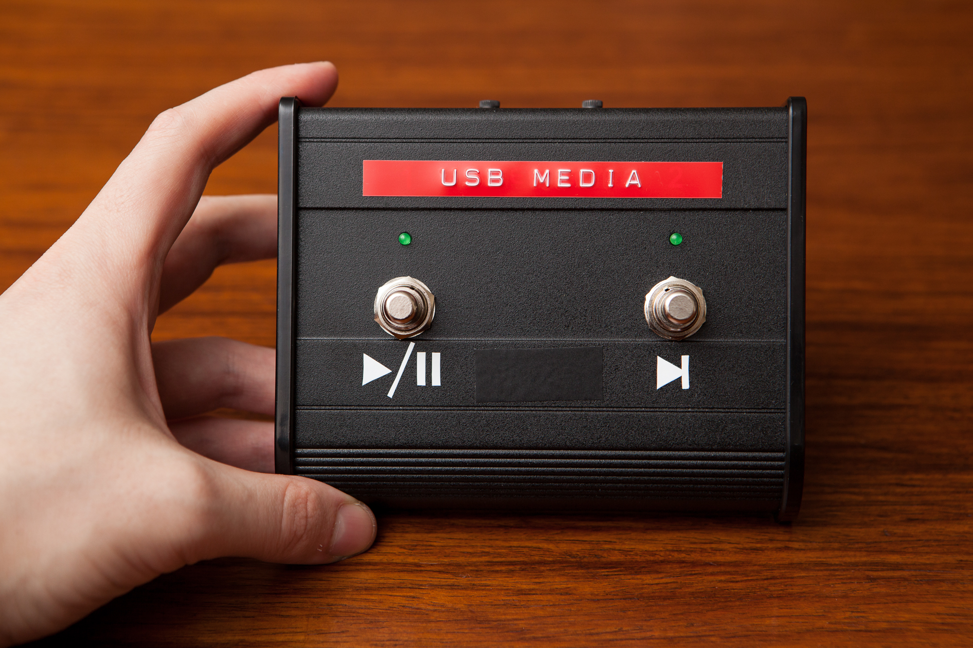
This is what I came up with: a two button footswitch controller that connects with USB and handles play / pause, next track, previous track, and volume.
Amp It Up
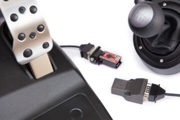
Earlier this year I completed a similar project, converting a sustain pedal into a keyboard switch for my PC. For that project I used a sustain pedal from an electric (piano) keyboard and connected it to an inline adapter with a microcontroller. Since this is going to live its life on the floor of my garage, I wanted to build something a little more robust and self-contained.
My inspiration came from guitar amplifiers. Some amplifiers have multiple inputs, and to switch between those inputs you can use a footswitch. These amplifier footswitches use latching single-pole double-throw (SPDT) switches that change the output of a 1/4″ tip-ring-sleeve (TRS) plug that connects to the amplifier. These footswitch assemblies are built to be rugged. They’re meant to be stomped on and abused, which is perfect for a workshop.
")
")
")
I picked up an inexpensive two-button footswitch from Amazon for less than $20. The reviews were less than steller, but they were mostly relating to compatibility with different amps. Since I’m tearing out the internals anyways I figure it’ll work fine.
Planning
Using a two button unit gives me a small device that’s easy to move around, but it also limits the number of controls I can use. To squeeze a little more utility out of it I decided to use a “number of presses” system, where the controller will do command one if pressed once, command two if pressed twice, etc. With a self-imposed limit of three presses per switch that gives me six total media commands.
Button 1 will handle the “no music” commands:
- Play / Pause
- Mute
- Volume Down
Button 2 will handle the “different music” commands:
- Next Track
- Previous Track
- Volume Up
I’m also going to make it so that holding a button triggers volume up / volume down, which allows me to make both fine and gross adjustments.
Hardware Modifications
The NW-202 switch comes nicely packaged with two latching switches, red LEDs, and a jack for a long male-male TRS cable. All of these things are going to be replaced to turn it into a media controller.
Disassembly
The first step was to pull everything out. The plastic end caps are each attached with three Phillips-head screws that are threaded into the extruded aluminum that makes up the majority of the enclosure. With the caps off, you can slide out the thin sheet metal that makes up the floor of the enclosure. This leaves the main portion: a piece of extruded aluminum that makes up the bulk of the enclosure and to which all of the functional components are attached.
Footswitch internals from the factory: two latching switches with LEDs, connected to a female 1/4″ TRS jack.
First to go were the LEDs. These are soldered directly to the switches so they light when the switches are latched “on”. They also have a dab of epoxy to hold them in place in their holes. A second with a soldering iron and a gentle tug frees them from the enclosure.
Next were the switches. Each has two wires: a shared ground and a ‘hot’ connection that is toggled with the switch. I desoldered these as well and then unscrewed the outside nuts using a 15 mm wrench, careful not to lose the nuts and washers. These switches can be reused in another project.
With the switches removed, the 1/4″ jack unscrews and then pops right out. This leaves just the base extrusion – ready for accepting new parts.
USB Support
With the enclosure empty, the first part to be added is the USB jack for the microcontroller. This is the only messy part of this build, so I’m doing it before I stuff any of the other parts into the case.
To keep a clean “OEM” look, I opted to use a panel mount jack in place of a hardwired cable. This allows me to move the box between different PCs without having to fish out cables, and lets me easily replace the cable in case there’s a fault.
The plug I’m using is a panel mount USB-B (female) to micro USB (male) cable. This specific product has a two advantages over most of the other panel mounted jacks I found:
- Straight to micro USB: fits the microcontroller I’m using. No splicing!
- Offset tabs: the mounting tabs are offset almost perfectly to the thickness of the enclosure’s back wall. This allows the jack to be flush with the outside of the case.
The length is a little long at 50 cm (~1.6 feet), but I opted to just coil it in the enclosure instead of cutting it open and shortening it. The differences between this and other panel-mount cables are minor all things considered, but every little bit goes towards the quality of the end product.
With USB cable in hand, the first order of business was expanding the round hole for the 1/4″ TRS jack to accommodate the rectangular USB port. I measured the USB jack’s dimensions, used a pair of calipers to trace them on a piece of masking tape on the enclosure, then used a needle file to carefully expand the opening. After a few minutes I had a healthy pile of aluminum shavings and a snug opening for the USB port.
I then secured the enclosure into my vise and placed the USB port on the outside facing in to mark to the mounting holes. I inserted a small punch into the mounting holes and lightly hammered to mark their position, then removed the jack and drilled them out using some oil and a 9/64″ drill bit. The holes were then deburred with a countersink.
USB port on the completed footswitch
The USB port was then re-inserted from the inside of the enclosure and securely attached with two M3 x 0.5 – 10 mm socket head cap screws with accompanying washers. These parts were then removed and set aside to wait on the other components, and the enclosure received a nice bath to clean it off.
I didn’t bother covering the enclosure’s foam “feet” while filing, and it got covered in aluminum dust that was quite happy to embed itself into the soft foam. Since I’m going to be using this on the floor of my garage this wasn’t a big deal, but if I had planned to use this somewhere where I was concerned about scratches I should have taken the time to cover the foam before filing.
Momentary Buttons
The latching switches that come with the footswitch are designed so that you can tap them once to change the amplifier’s mode. Press it once and contacts 1/2 are connected, press it again and contacts 2/3 are connected. For this project I want to be able to tap the switches multiple times or even hold them down to send commands, which isn’t really possible with latching switches that only change states on press and not on both press and release.
I ordered some replacement SPST momentary switches that have the same form factor as the latching ones. This lets me re-use the mounting holes and keep the same aesthetic. I re-used the nicer washer stack from the latching switches and tightened them in place. Since the top face of the extrusion is sloped, the main body of the switch is facing “up” towards the back of the case on the inside which gives me more room to work. It also positions the contacts above the LED holes so they can share a ground connection without running another wire.
LEDs
The original switch comes with a pair of diffused 3 mm red LEDs with inline 470 Ω resistors. I wanted my media switch to have a “friendlier” feel, so I opted to remove these and replace them with nicer green LEDs.
All 3 mm LEDs are roughly the same size so this was more or less a drop-in replacement. I soldered a 22 kΩ resistor (spec’d for brightness) to the negative lead and then attached it to the switch ground. The soldered leads will keep the LED in place in its hole but shouldn’t be stressed, so I added a dab of 5 minute epoxy to keep things secure. I also re-used the insulating tubing from the existing LEDs to keep the leads separated.
Microcontroller
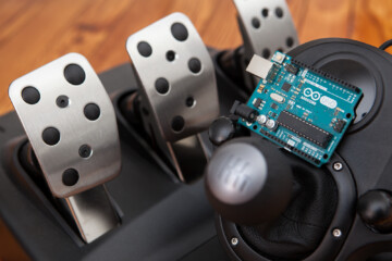
The final step for the electronics was to add the microcontroller. I’m using one of my favorite Arduino Pro Micros that uses the ATmega32U4 microcontroller, which is inexpensive and has native USB support. Rather than building a custom circuit board, using an off-the-shelf Pro Micro is cheaper and easier.
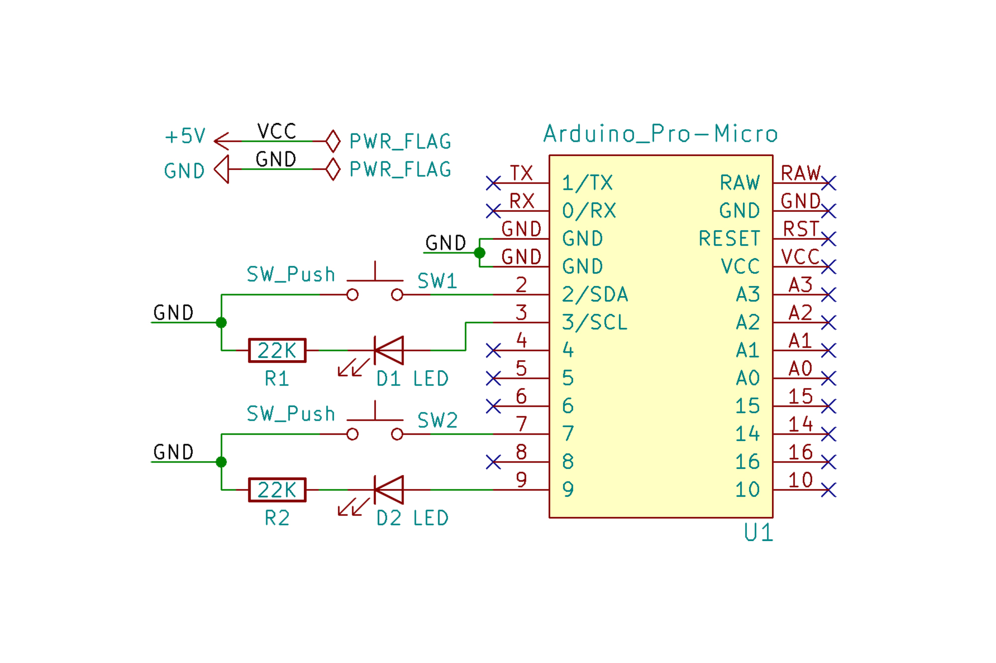
The circuit is essentially a “dead bug” construction, with the LEDs and resistors attached directly to the switches. The switches are normally open and connect to ground, using the ATmega32U4’s built-in pull-up resistors to pull them high. The LEDs source power directly from dedicated I/O pins, which allows me to control them even when the buttons are released.
I’m using PWM-capable pins for the LED outputs in case I ever want to reduce the LED brightness, and interrupt-capable pins for the buttons if I ever want to re-write the code to use interrupts. There’s no issue running the microcontroller without interrupts (particularly with the press counter timeout delay), but I may as well be smart about it.
I connected everything together with some stranded 30 AWG wire, taped the wires in bundles using some Kapton tape, and then attached the microcontroller to the case using some heavy duty 3M foam tape. The microcontroller is attached to the main extrusion as well, which makes it possible to remove both endcaps and the base plate from the enclosure without having to disconnect any wires.
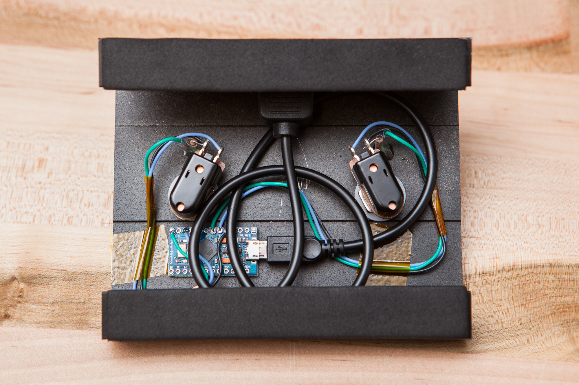
With that, all of the hardware modifications are complete! After this photo was taken I put a couple of strips of electrical tape over the microcontroller as a precaution in case the mounting tape ever gives way, then slid the base plate back on and screwed the side covers into place.
Programming
The programming for this was pretty straight-forward: read the pin states for the buttons, count the number of “presses” in a given timeframe, and then send the appropriate media command over USB to the PC. Using the Arduino framework here made programming the device simple, especially since the bootloader allows updates over USB.
I’m using Nico Hood’s HID library to handle the media commands. The library provides easy access to the “Consumer” HID report usage, which among other things includes controls for Play / Pause (0xCD), Next Track (0xB5), and Previous Track (0xB6). These can be set with a simple press or release function call with the proper usage ID, conveniently provided by an enum. From there I just needed to write a small class to check how many times a button was pressed, relate that to a specific command, and I was done.
Believe me when I say the code isn’t very interesting, so there’s not much point in talking about it here. Each part is fairly simple in its own right, but when you stack them all up the resulting code is relatively long and tedious. The HID portions in particular are a bit of a mess, if only because the pseudo-singletons the library uses for each usage type aren’t all that easy to pass around without screwing up the USB descriptor.
If you’d like to take a look at the source, the full code is on GitHub and licensed under MIT.
Button Mode
One of the last-minute additions to the code that is worth talking about was the inclusion of a “mode” setting, saved and recalled using the microcontroller’s EEPROM. This setting allows the controller to switch between “media” and “keyboard” modes, disabling the media controls and allowing me to use the device as a generic keyboard device sending hidden function keys (F21 and F22).
To switch modes, hold both buttons as the device is plugged in. If both buttons are held for two seconds, the device will blink 10 times to let the user know that the mode has been switched. The current mode is saved in the EEPROM and will persist through disconnects. This check is only done on startup to prevent issues where the user may need to hold down both buttons at the same time.
Making Things Pretty
With the microcontroller programmed, the final step was to get rid of the “Neewer” graphics and stylize the box by adding some on-theme labels.
In the spirit of a modified amplifier pedal and in my own mini tribute to Back to the Future, I covered up the white “Neewer” text and the button numbers with a 3/8″ embossed red label across the top that reads “USB MEDIA”. For each button I designed a small 3/8″ label for their primary function in Adobe Illustrator and cut it out of Oracal 651 white vinyl by hand using a craft knife. Lastly, the “NW-202” label between the buttons was covered up with a small piece of matte black Oracal 631 vinyl.
Conclusion
Project complete! I’ve been using this for a week or so now and it works perfectly. It takes a little while to internalize which button presses do what, but once you get that down it’s a breeze to use. It’s also built like a tank, and should hold up great down in the garage.
Total cost was approximately $45, excluding the tiny bit of vinyl and the LEDs I already had on hand. I could’ve saved some money by using a different footswitch that already had momentary buttons or building my own enclosure, but I had my heart set on a traditional amplifier switch like this.
This is going to be the last project of the year. See you in 2019!
Parts List
Following tradition, I’ve linked various parts throughout the post as they’re used. But since it’s often useful to have everything in one place, here’s a complete list:
- Two-button amplifier footswitch
- 2x stomp-box sized SPST momentary switches
- 2x 3 mm green LEDs
- Panel-mount USB-B to micro USB cable
- 5V Arduino Pro Micro
- White vinyl (labels)
- Black vinyl (covering labels)
Note that these are Amazon affiliate referral links, which help fund the content on this site. Thank you for your support!

5 Comments
Sam · October 14, 2020 at 6:09 pm
This is awesome! Thanks for the build. About to build my first PC and had something similar in mind. This will definitely help. Thanks.
Dave · October 14, 2020 at 9:51 pm
Thanks! It’s been almost two years and I still use this every day. Let me know what you make!
Deni · April 11, 2023 at 8:20 pm
Hi Dave!
I came across this project of yours. I would like to build one similar to it but with the switching options:
Button 1:
Single tap – Rewind for 5 seconds
Double tap – Slow playback (0.75 speed) or decreases by 25% for every double tap. Lowest speed is capped at 50%.
Press and hold – Fast rewind
Button 2:
Single Tap – Play and pause
Double Tap – Faster playback (1.25 speed) or increases by 25% for every double tap. Maximum speed is capped at 200%.
Press and hold – Fast forward
Is it possible using the same parts as listed?
Thanks in advance.
Dave · April 11, 2023 at 8:57 pm
Hi Deni. If all you want to change is the device’s output there should be no required hardware changes. You would need to do some research for what keyboard shortcuts or USB commands are necessary for the software outputs you have planned.
Deni · April 13, 2023 at 8:03 pm
Hi Dave. Thanks for the quick reply. I haven’t dive into arduino/mcu programming. 🙂 Although i have checked the USB HID usage tables and came across this:
ID Usage Name Usage Type
B0 Play OOC
B1 Pause OOC
B3 Fast Forward OOC
B4 Rewind OOC
BD Tracking LC
BE Track Normal OSC
CA Tracking Increment RTC
CB Tracking Decrement RTC
CD Play/Pause OS
I might need to undergo Arduino 101. 😀