I keep getting distracted by other projects and ideas, but I wanted to post a brief update on the footwell NeoPixels project. I’ve been working on the data structures and color patterns, but today I wanted to cover something simpler.
For the time being I’m not planning on changing the color of the tC’s interior lighting, which is a nice burnt orange. I’ve toyed back and forth with the idea of replacing the tC’s cubby light and adding a few lights to the cupholders, which on a default setting should match the rest of the lighting. This gives us today’s problem: how do we match the NeoPixel’s color with the other LEDs?
We could do this scientifically by comparing the datasheets on the LEDs and the relative light outputs / color temperatures, but because this just has to look more-or-less right (and I can always change it later!) we’re going to do this the quick and dirty way: we’re going to eyeball it with color blending.
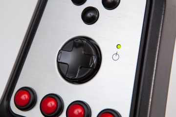
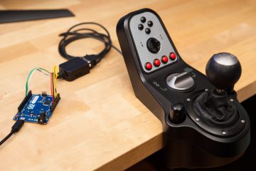
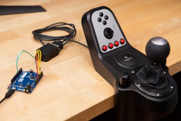
I put together a quick color blending rig using a protoshield and three 10k potentiometers on top of the NeoPixel prototyping board. I then wrote a short sketch that takes the analog outputs from each potentiometer and converts them to an 8-bit value, sets the NeoPixel colors, and sends the RGB data over serial for logging. See below:
#include <Adafruit_NeoPixel.h>

#define rPin 0
#define gPin 1
#define bPin 2

#define numPixels 8
#define neoPin 6

Adafruit_NeoPixel strip = Adafruit_NeoPixel(numPixels, neoPin, NEO_GRBW + NEO_KHZ800);

void setup() {
  Serial.begin(9600);
  strip.begin();

  strip.setBrightness(50);
  strip.show();
}

void loop() {
  char msg[64];
  uint8_t r, b, g;

  //Converts analog 4-bit value to 8-bit.
  r = analogRead(rPin) / 4;
  g = analogRead(gPin) / 4;
  b = analogRead(bPin) / 4;

  sprintf(msg, "R: %3u G: %3u B: %3u", r, g, b);
  Serial.println(msg);

  for(int i=0; i<numPixels; i++){
    strip.setPixelColor(i, r, g, b);
  }

  strip.show();
}
I parked the tC in my garage, turned off the lights, and tried to match the color the best that I could. From our previous understanding of color mixing we can figure-out our starting point. We know that orange is yellow with more red (or with less green, if you prefer), and that yellow is the opposite of blue (and therefore a combination of red and green). That means we set the blue dial to 0, the red dial to max (255), and then adjust the green dial until it matches. With thirty seconds of tweaking, we have a color that looks right!
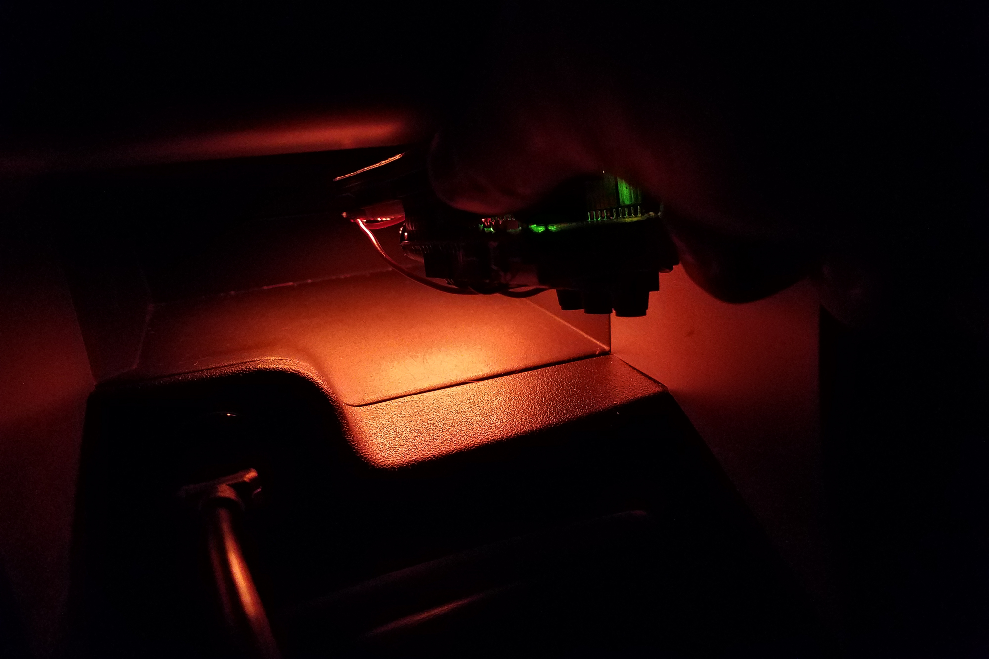
I took the board back to the computer, making sure I didn’t touch the potentiometers and the color is:
R: 255 G: 35 B: 0
Easy! Now I just need to keep plugging away on the rest of the patterns (including the CAN-enabled ones!).
Update: December 20th, 2016
I rewrote the code to use the FastLED library, if you’re using a supported device (I’m working with WS2812B LEDs on the Adalight project). In case it’s useful to anyone, I’ve included the code below.
#include

#define rPin 0
#define gPin 1
#define bPin 2

#define numLEDs 80
#define ledPin 6

CRGB leds[numLEDs];

void setup(){
  Serial.begin(9600);

  FastLED.addLeds<WS2812B, ledPin, GRB>(leds, numLEDs);
  FastLED.show();
}

void loop() {
  char msg[64];
  uint8_t r, b, g;

  //Converts analog 4 byte value to 1 byte.
  r = analogRead(rPin) / 4;
  g = analogRead(gPin) / 4;
  b = analogRead(bPin) / 4;

  sprintf(msg, "R: %3u G: %3u B: %3u", r, g, b);
  Serial.println(msg);

  for(int i=0; i<numLEDs; i++){
    leds[i].r = r;
    leds[i].g = g;
    leds[i].b = b;
  }

  FastLED.show();
}