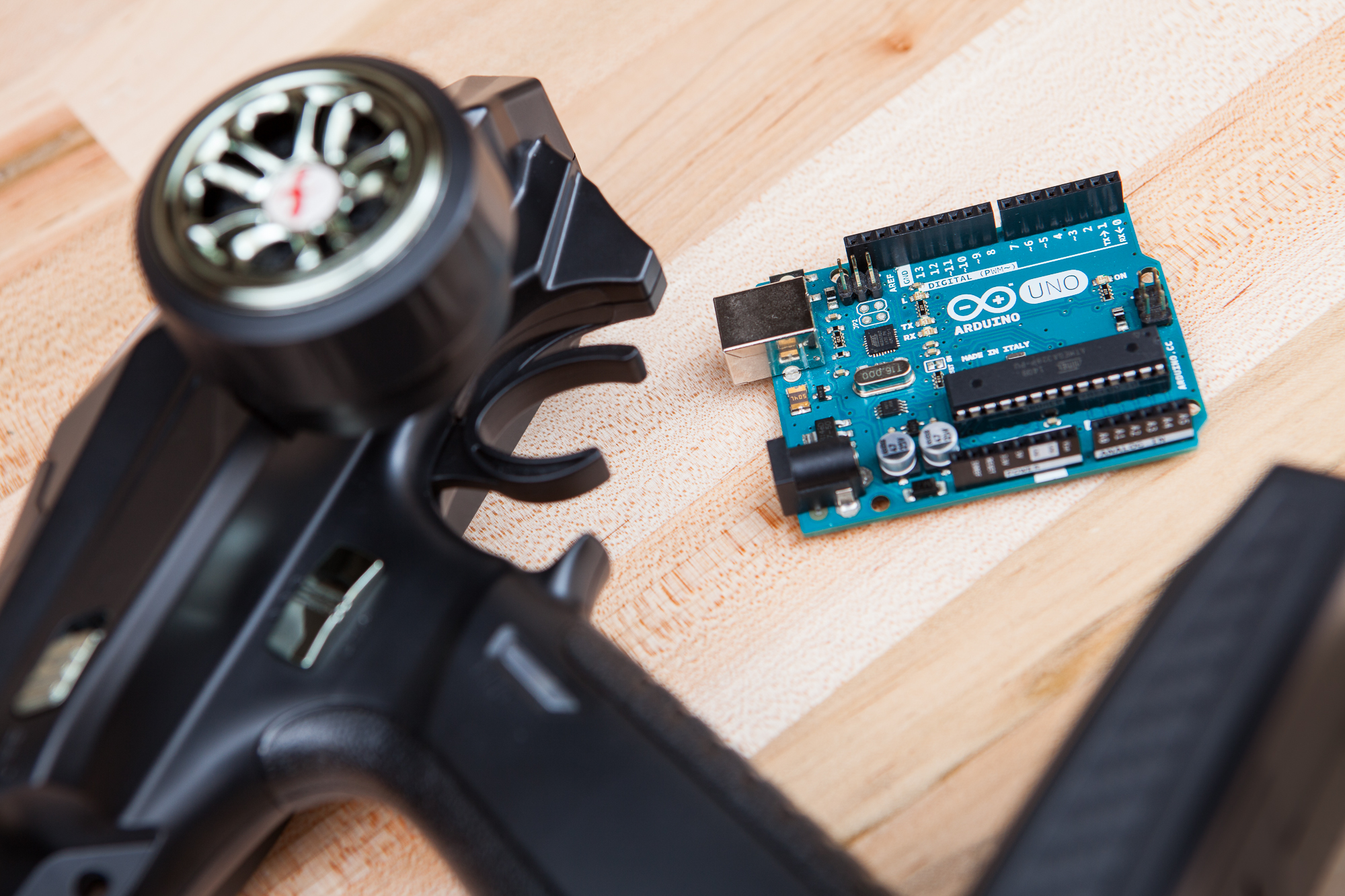
Whether you’re modifying a remote controlled vehicle or creating something completely new, Arduino boards are a great way to expand the functionality of your RC receiver. Adding a microcontroller lets you program complex logic functions, sound effects, lighting animations, and more – all managed from the comfort of a wireless remote.
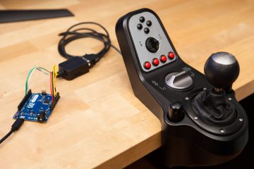
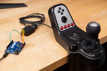
In this tutorial I’m going to show you how to connect a PWM-based RC receiver to an Arduino and read data from it using the Servo Input library.
Gathering Materials
For this tutorial you’ll need a few components:
If you don’t have an RC controller and receiver handy, you can also use a second Arduino with the Servo library instead. In this case you’ll need male to male jumpers instead of male to female.
Note that the above list contains Amazon affiliate links which help fund the content on this site. Thank you for your support!
Making Connections
The majority of RC receivers are designed to drive servo motors and use what are called pulse-width modulated (PWM) signals. The connections are arranged in a line of 3 pins, repeated by however many channels your receiver has. In order, these are:
- Signal (⎍)
- Power (+)
- Ground (-)
These connections should be labeled somewhere on your receiver. Power will always be in the center, but signal and ground may be ‘flipped’ depending on the orientation of your receiver. Some receivers have a “Futaba” notch so you can’t plug the servos in backwards. This notched cutout will be next to the signal pin.
Caution: Voltage Levels
Before anything else we need to check the acceptable voltage levels for both the receiver and the Arduino. Too little voltage and signals may not be picked up properly. Too much voltage and something might get damaged!
The operating voltage of your receiver should be listed in the manual or on the product page if your purchased it online. My DUMBORC X6F receiver for instance has a voltage range of 4.8V – 10V, so it will work fine with the 5V power from an Uno.
Most Arduinos, like the Uno and Leonardo, run at 5V and accept inputs up to 5V on their I/O pins. Though some boards like the Due, the Teensy, and the ESP variants run at 3.3V and will be damaged if you connect a 5V signal. If you’re unsure, look up the operating voltage for your board before connecting anything!
If the operating voltages do not overlap, meaning that the operating voltage of the receiver is either higher or lower than the Arduino’s, then you will need to power the receiver separately and use a level shifter or a voltage divider on the signal line.
Power
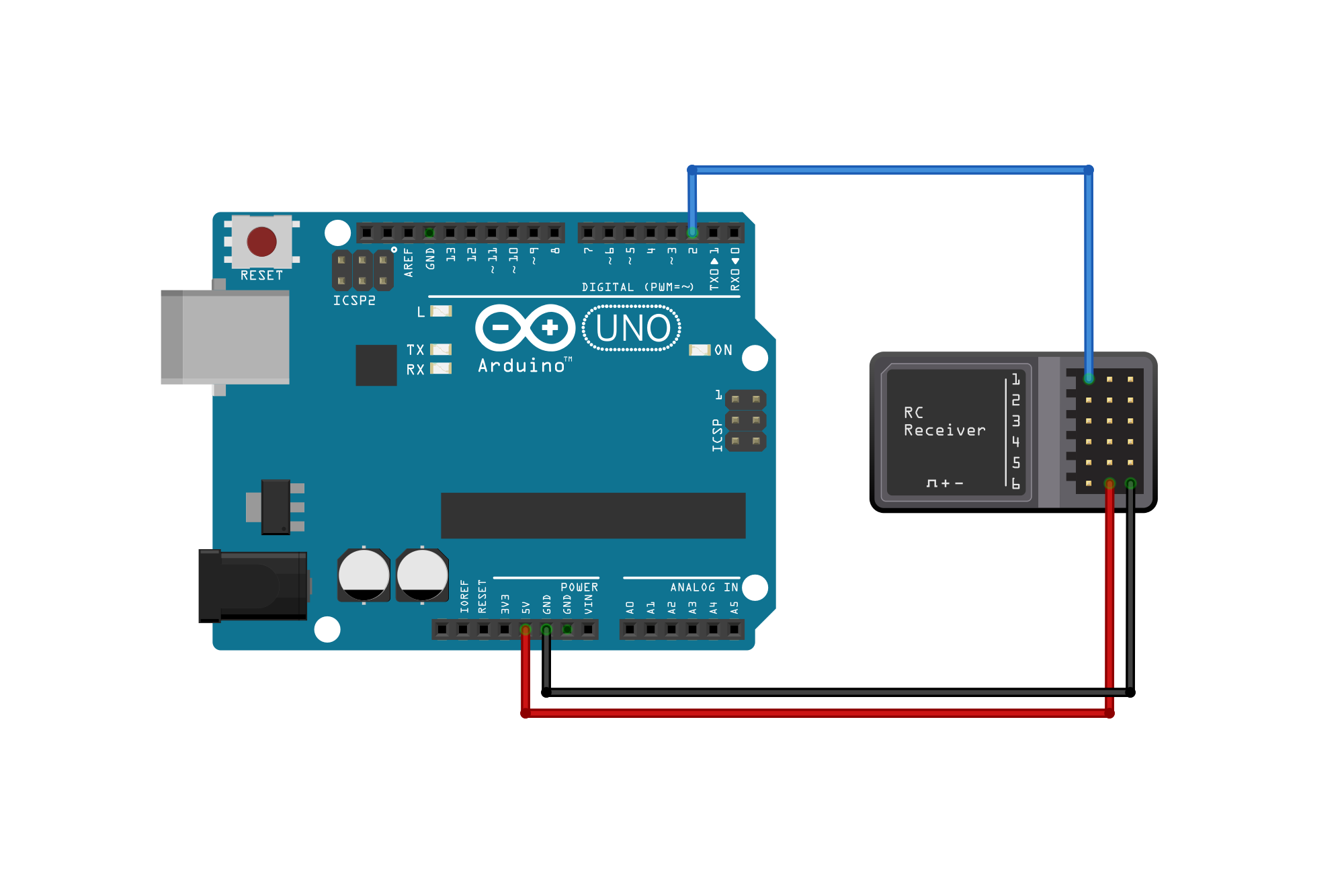
The first connection to make is power. On the receiver this is the middle pin for the 3-pin connector. Most receivers have all of their ‘power’ pins tied together, so it doesn’t matter which row you connect to. Both the Arduino and the receiver need to be powered, though they do not need to share a power supply.
If your receiver is not powered separately it can be powered by the Arduino so long as the operating voltages overlap. For example, a 5V Arduino Uno can power my X4F receiver which works between 4.8V and 10V. Connect one of the servo ‘power’ pins on the receiver, the middle of a 3-pin row, to the ‘5V’ (or equivalent operating voltage) pin on the Arduino.
If the receiver is powered and your Arduino isn’t, you can connect the power from the receiver to the regulated ‘Vin’ pin on the Arduino so long as the supply voltage is less than 12V.
If both the receiver and the Arduino have separate power sources, you do not need to connect a power wire between the two boards.
Ground
Next up is the ground connection. This one is easy: connect the grounds between the two boards – GND on the Arduino to ground on the RC receiver (‘right’ pin in a 3-pin row). As with power it doesn’t matter which row (channel) this connects to.
Connecting the grounds is critical. If the receiver doesn’t turn on or the signal data is corrupt, this is the first place to look.
Servo Signals and Interrupts
| Board | Digital Pins Usable for Interrupts |
|---|---|
| Uno, Nano, Mini, other 328-based | 2, 3 |
| Uno WiFi Rev.2 | all digital pins |
| Mega, Mega2560, MegaADK | 2, 3, 18, 19, 20, 21 |
| Micro, Leonardo, other 32u4-based | 0, 1, 2, 3, 7 |
| Zero | all digital pins, except 4 |
| MKR Family boards | 0, 1, 4, 5, 6, 7, 8, 9, A1, A2 |
| Due | all digital pins |
| 101 | 2, 5, 7, 8, 10, 11, 12, 13 |
This is the trickiest part of the setup: connecting the servo signal pins to the Arduino.
For the best results the servo channel’s signal pin should be connected to a pin on the Arduino that is capable of external interrupts. This allows the Arduino to read the servo’s position in the background without disturbing your program.
The table above shows the interrupt capable pins for some common Arduino boards. On the Uno, pins 2 and 3 are capable of interrupts. Connect the signal pin (‘left’ in the 3-pin row) to an interrupt capable pin on the Arduino. For this tutorial I’m using pin ‘2’ on my Uno.
If you need more channels than the number of available interrupt pins, hope is not lost! You will need to use “pin change” interrupts instead. On the Uno all pins support “pin change” interrupts, although they are slower and less accurate.
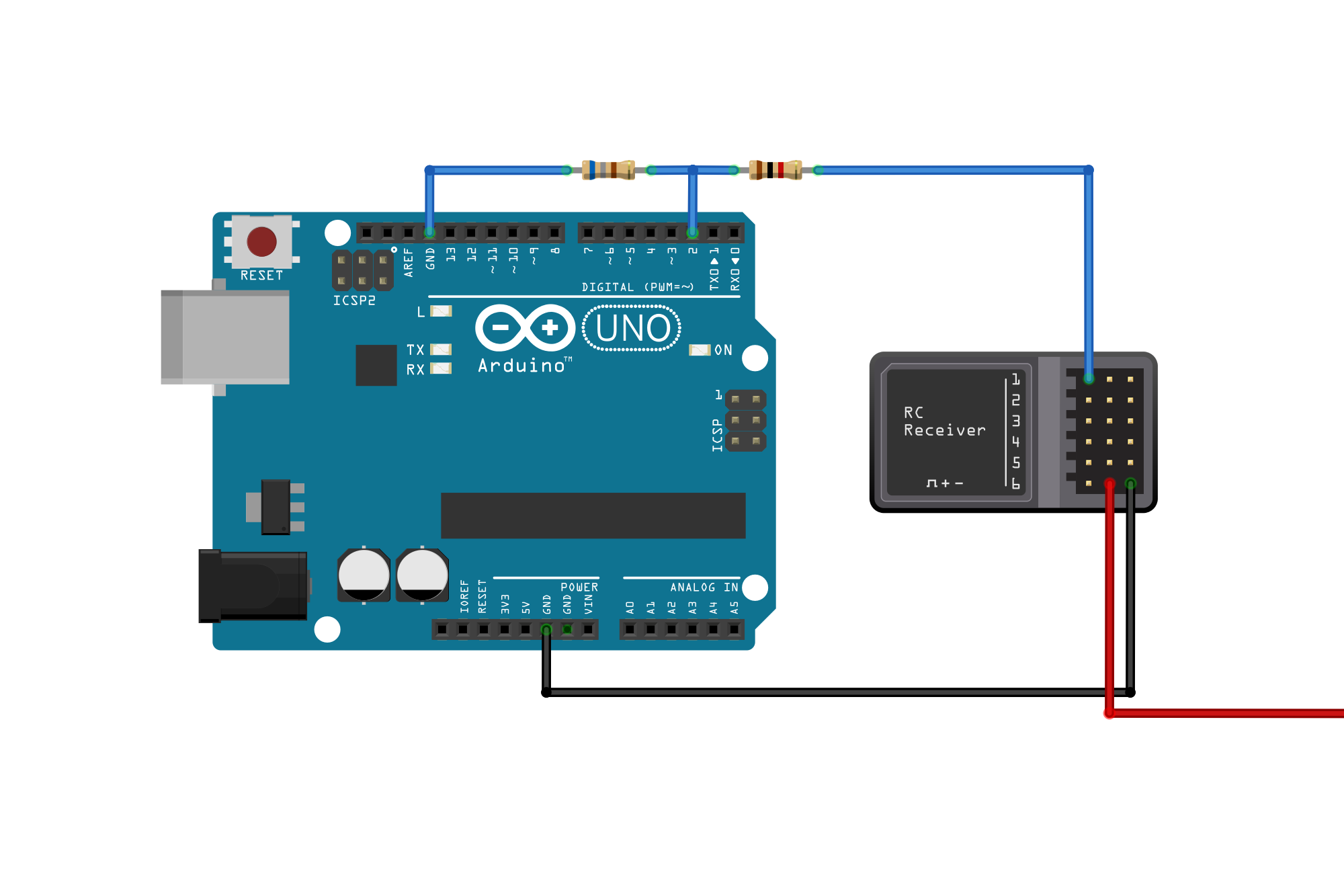
If the receiver is being powered with a higher voltage than the Arduino’s you will need to ‘shift’ the signal to a lower voltage. To do this you can either use a level shifter or a simple voltage divider. How to wire a level shifter or voltage divider is beyond the scope of this tutorial, although our friends over at SparkFun have some useful resources.
Because it bears repeating: if your receiver is powered by a higher voltage than the Arduino, you must shift the signal voltage. Not doing so will permanently damage or destroy the Arduino.
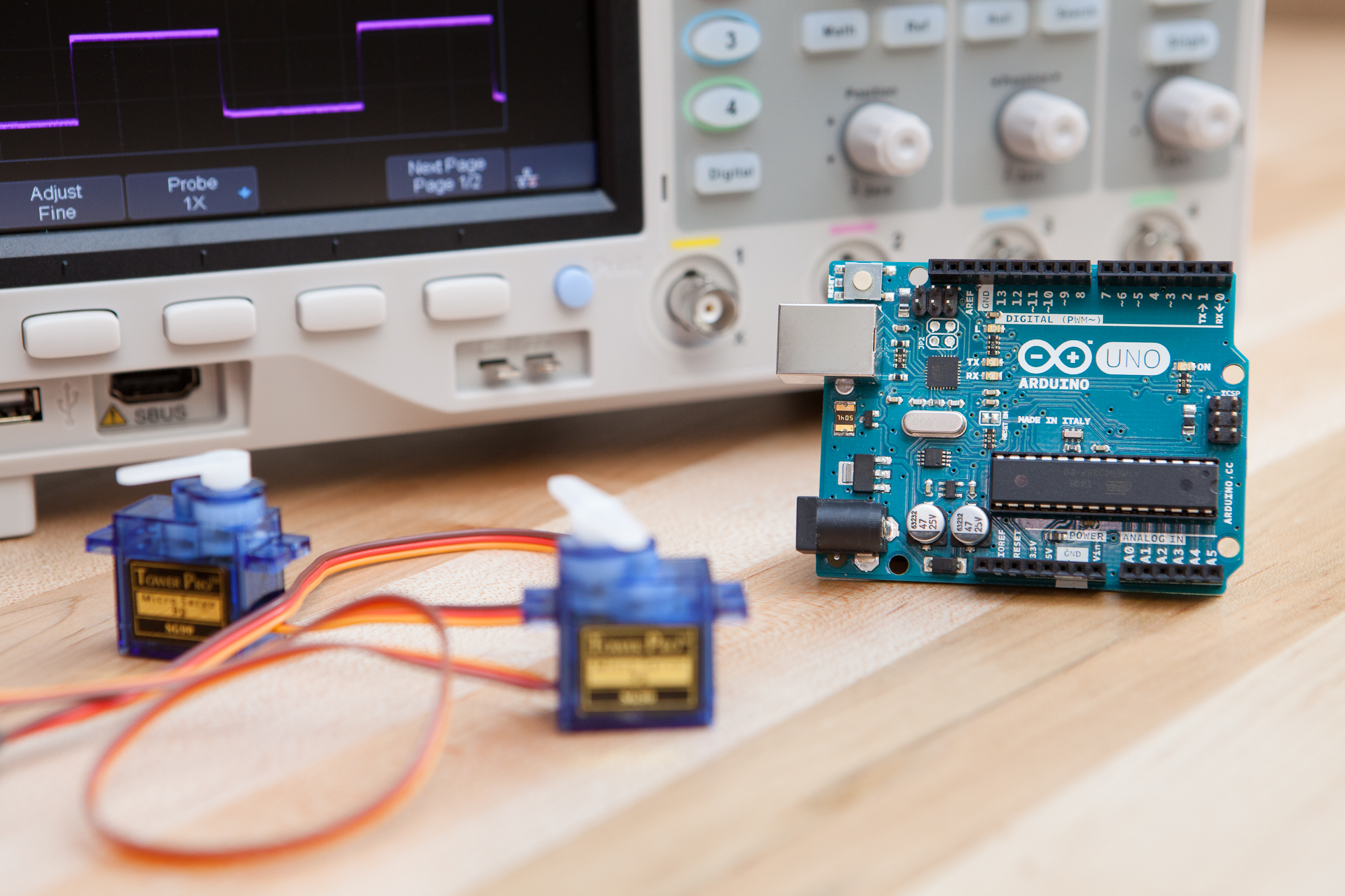
That’s it for hardware. Now let’s take a look at the software needed to allow the Arduino to “talk” to the RC receiver.
The Servo Input Library
To make this easier we’re going to use a library called ServoInput, which was created specifically to read signals from PWM-based RC receivers. It takes away all of the effort in having to program the signal reading code yourself. It’s also open source so you can use it in your own projects without issue.
The Servo Input library can be downloaded through the Arduino IDE libraries manager or directly from GitHub and installed via .zip.
If you are not using an interrupt capable pin (see ‘Servo Signals and Interrupts’ above) you will also need to download NicoHood’s PinChangeInterrupt library.
“But what if I don’t want to use a library?”
In that case you have two options: you can either use the blocking function pulseIn which will take up to 20 ms to read each channel, or you can write your own interrupt function to read the pulse width. Both of those methods are beyond the scope of this tutorial.
“Hello World”
Let’s start with a simple example to get the ball rolling. Open up the “BasicAngle” example from the ServoInput examples folder. It should look something like this:
#include <ServoInput.h>

ServoInputPin<2> servo;

void setup() {
	Serial.begin(115200);
	servo.attach();  // attaches the servo input interrupt

	while (servo.available() == false) {
		Serial.println("Waiting for servo signal...");
		delay(500);
	}
}

void loop() {
	float angle = servo.getAngle();  // get angle of servo (0 - 180)
	Serial.println(angle);
}
You can see that pin <2> is defined at the top. This should match the pin number you connected the signal wire to.
If you are using an Uno but are not using an interrupt capable pin, you need to include the PinChangeInterrupt library mentioned above to add support for other pins. See the PinChangeLib.ino example from the library for more detail.
Upload this sketch to the Arduino and open up the serial monitor, then turn on your RC remote and try changing the control for the connected channel. If all is well, you should see the virtual servo angle being printed to the serial monitor and changing with your controller.
Calibration
The next step once everything is up and running is to calibrate the input range. By default ServoInput assumes servo pulses to be between 1000 µs and 2000 µs long, with the ‘center’ position at 1500 µs. Many receivers can go beyond this range though, and calibrating to the exact range of your receiver makes the output more accurate.
You can use the “Calibration” example from the library to get these min and max values – just run the example, move the input to its extremes, and then write down output from the serial console. The range can then be set either in the constructor:
ServoInputPin<2> ch(1000, 2000);
Or in the setup() function:
ch.setRange(1000, 2000);
If you want the output to reliably hit the extremes, it’s helpful to be conservative here and take a few microseconds off of either end.
Examples
Now let’s go through a few examples for how to use an Arduino and the Servo Input library to parse data from an RC receiver.
Turning on an LED / Pin
We’ll start simple: lighting an LED based off of an RC receiver input:
#include <ServoInput.h>

ServoInputPin<2> ch;
const int LED_Pin = LED_BUILTIN; // built-in LED (pin 13 on Uno)

void setup() {
	pinMode(LED_Pin, OUTPUT);
	ch.attach();
}

void loop() {
	boolean state = ch.getBoolean();
	digitalWrite(LED_Pin, state);
}
This works by reading the servo’s position and mapping it to a boolean. If it’s above the midpoint of the range the output is ‘true’, if it’s below the midpoint it’s ‘false’.
If you need finer control over when the output is triggered, just read the position as a percentage and compare it against a threshold. Using the same setup and global variables as above:
const float threshold = 0.7; // 70%

void loop() {
	float percent = ch.getPercent();

	if(percent >= threshold) {
		digitalWrite(LED_Pin, true);
	}
	else {
		digitalWrite(LED_Pin, false);
	}
}
Or more succinctly:
const float threshold = 0.7; // 70%

void loop() {
	boolean state = (ch.getPercent() >= threshold);
	digitalWrite(LED_Pin, state);
}
Because this just writes the output state of a pin, you could also use this for remotely controlling any digital (on/off) device with a transistor or relay: DC motors, buzzers, oil slicks, control surfaces, etc.
Reading a Multi-Position Switch
Many RC controllers, particularly advanced ones, include switches with multiple positions to give you finer control over a motor’s setting. The library can easily read these switches using the built-in map function:
#include <ServoInput.h>

ServoInputPin<2> ch;
const int NumPositions = 3;

void setup() {
	Serial.begin(115200);
	ch.attach();
}

void loop() {
	int position = ch.map(1, NumPositions);
	Serial.print("Switch Position: ");
	Serial.println(position);
}
Edit the NumPositions variable to change the output range. If you find that this is inconsistent or doesn’t properly match your switch positions, your timing calibration may be off (see “Calibration” above).
Separating Throttle and Brake
Another common problem is parsing the data from a bidirectional analog input. That is to say, an analog input that has two possible directions like a steering wheel (left/right) or a speed control (throttle/brake). This is easy to do in the library by using the map function and a symmetrical range:
#include <ServoInput.h>

ServoInputPin<2> ch;

void setup() {
	Serial.begin(115200);
	ch.attach();
}

void loop() {
	int speed = ch.map(-100, 100);

	if(speed >= 0) {
		Serial.print("Throttle: ");
		Serial.print(speed);
	}
	else {
		Serial.print("Brake: ");
		Serial.print(abs(speed));
	}
	Serial.println("%");
}
This maps the position from -100 to 100. Positive values are for throttle, while negative values are for braking.
There’s a slight problem here, as the position will flip-flop between ‘throttle’ and ‘brake’ when it’s around the center. To fix this we can replace the plain map function with mapDeadzone, which will center (zero) the output within a percentage range of the middle without affecting the overall output range:
const float Deadzone = 0.15;  // 15%

void loop() {
	int speed = ch.mapDeadzone(-100, 100, Deadzone);

	if(speed == 0) {
		Serial.println("In deadzone!");
	}
	if(speed > 0) {
		Serial.print("Throttle: ");
		Serial.print(speed);
		Serial.println("%");
	}
	else {
		Serial.print("Brake: ");
		Serial.print(abs(speed));
		Serial.println("%");
	}
}
Multiple Channel Inputs
ServoInput makes it just as easy to read from multiple channels as it is to read from just one. All you need is a second ServoInputPin object set to a different pin:
#include <ServoInput.h>

ServoInputPin<2> ch1;
ServoInputPin<3> ch2;

void setup() {
	Serial.begin(115200);
	ch1.attach();
	ch2.attach();
}

void loop() {
	Serial.print("Ch1: ");
	Serial.print(ch1.getAngle());

	Serial.print(" Ch2: ");
	Serial.print(ch2.getAngle());

	Serial.println();
}
The library also features a ‘manager’ class (ServoInput) that has utility functions like allAvailable or anyAvailable if you want to check all of the channels at the same time:
if(ServoInput.allAvailable()) {
	Serial.println("All channels have data!");
}
else if(ServoInput.anyAvailable()) {
	Serial.println("At least one channel has data!");
}
For advanced users, all ServoInputPin objects use a base class called ServoInputSignal which includes a linked list for iterative access:
ServoInputSignal* ptr = ServoInputSignal::getHead();

while(ptr != nullptr) {
	Serial.print(ptr->getAngle());
	Serial.print('\t');
	ptr = ptr->getNext();
}
Serial.println();
Further Reading
This hopefully gave you a primer for how to get started with adding RC receivers to your Arduino projects. For more info, I would recommend reading the Servo Input library documentation and source code on GitHub.
What have you made with Arduino and RC controllers? Share in the comments below!

30 Comments
Alex Sin · October 24, 2020 at 11:04 pm
if you want to replace the circuit board in the DumboRC-X6 in that picture with an arduino itself check out this:
https://easyeda.com/bigbangus/dumborc-x6-nano-v3
https://easyeda.com/bigbangus/dumborc-x6-trigger-button
Now you have full control 🙂
Pete · January 25, 2021 at 5:31 pm
Any thoughts on adding another parameter for mapping RC controllers with non-centered/linear throttles?
Dave · January 25, 2021 at 5:33 pm
In what way do you mean? Wouldn’t those be covered by the `getPercent()` function?
Pete · January 27, 2021 at 12:14 am
For instance, I ran a calibration on my throttle channel and got:
Min(Full Reverse)/Nominal (No Input)/Max (Full Forward): 1332/1500/1900
So the resolution for reverse is 168, while forward is 400.
Dave · January 27, 2021 at 3:05 am
Ah I gotcha. I thought you meant downward throttle joysticks, like on drones and RC airplanes.
That’s a tricky problem, because it introduces a lot of other questions for the other mapping functions. The library is hardware agnostic and knows nothing about what’s connected on the other end. Telling it that “there is a center different than you think” is a little strange because it implies that it needs to treat the two halves of the range differently without telling it how to treat them.
For example, with your range how would an arbitrary map evaluate? Would it map the entire range? Create a split in the middle and use two linear scales? Try to fit a curve?
Or with the deadzone functionality. The deadzone functions take a percentage as an argument which tells them how “wide” the deadzone is in the range. If the resolutions are unequal, how does a deadzone percentage work if the total range has uneven components? Is it a percentage of the total range, of the smallest or largest range, or is it applied unevenly to both halves?
Because the library is meant to work with any sort of servo input and not just RC controllers, I don’t have a good answer to those questions which works for all applications. That makes it hard to write a useful implementation for the library.
For your specific controller you know best for how you want to use the output data. I’d recommend writing your own mapping function using the pulse values from the library, or building your own derived class that inherits from ServoInputPin<>.
Pete · January 28, 2021 at 11:30 pm
Forked your repo – seems to work with minor change..
Dave · January 29, 2021 at 4:53 am
Nice! Another win for open source.
Paul Clay · March 5, 2021 at 11:05 am
Thanks for you work and this is really helpful. I was wondering if you can pull the raw pwm pulse length data, as opposed to the % throttle or deg angle. I have noticed you have done it with the calibration program, but I can’t seem to get it to work as a stand alone program.
Dave · March 5, 2021 at 11:07 am
Hi Paul. You should be able to do that using the `getPulseRaw()` function.
Paul Clay · March 5, 2021 at 11:14 am
Sorry I don’t know how to do that
Dave · March 5, 2021 at 11:16 am
See the examples above, and just replace the function call:
Paul Clay · March 5, 2021 at 11:19 am
Cheers, I’ll have another go
Doc · May 11, 2021 at 11:07 pm
This is almost what I’m looking for! I’m trying to make an RC FPV platform using Arduino being controlled by an RC transmitter and receiver (I’m using a Turnigy 9X with an iA10 receiver). I’m trying to figure out how I’m going to hook up and power the FPV system (a small camera with the VTX/antenna built into it). It has a servo plug for power. I’m also looking at installing LEDs on this little “tank” as well… Could you point me in the right direction as far as this goes?
Paw Paw · June 15, 2021 at 12:17 pm
Dave, Thank you so much for explaining this in the simplest of terms. I’m over 60 and trying to get a handle on getting these pocket puters up and running. (can’t let the grandkids out smart the ol’ man) Been monkeying with RC since the 70’s. Remember escapements? Any links to other useful tutorials would be great. Thanks again!
Jose Antonio · August 17, 2021 at 7:21 am
Dave,
Thank you for this information. As someone who’s just starting to learn Arduino and wanting to control a DIY tracked robot with an RC controller your article was informative, although a bit out of my depth.
You’re using servos in this article and I was wondering what would be the difference if instead, as in my case, you were using 2 dc motors?
Peace
Dave · August 17, 2021 at 8:20 am
Hi Jose,
Apologies if I’m misunderstanding you, but there are no physical servos here – the RC receiver just outputs data that is normally used for servos. To control DC motors on the Arduino you would use the same methods to read the would-be servos’ positions from the RC receiver’s output, then set the DC motor outputs accordingly.
Jose Antonio · August 18, 2021 at 7:53 pm
Dave,
Thank you for your reply, much appreciated.
I get that there are no physical servos yet the code, even for led’s, references servos (ServoInputPin ch;).
Am I to understand that even though I’m using a dc motor or even an led that I would still reference them by using ServoInputPin ch; ?
Dave · August 19, 2021 at 1:39 am
Yes, exactly. The library is called “ServoInput” because it’s for reading the PWM signals that drive servo motors. Most RC receivers are designed for driving 3-pin servo motors directly, so you can connect to the RC receiver and read the position of the “servo motor” that’s being commanded by the remote even without a servo motor physically present. The library just fetches the data from the pin, it doesn’t care what you connect on the other side.
Jose Antonio · August 21, 2021 at 2:17 pm
Dave,
Got it, thank you.
Still much to learn, looking forward to it.
Peace,
ihsoil · November 12, 2022 at 7:30 pm
Thanks for this good project !
I read receiver of car rc transmitter, throttle and wheel work perfectly, i read angle precisly. But i have on the transmitter a momentary button and when i press and hold it I get (with ch.getBoolean()) : 1 and then 0, 0, then 1 and 0,0,0,0, 1,0,0,1,0,0,… etc.
I want always 1, and 0 when button is released… is it possible, and how ?
Dave · November 12, 2022 at 11:59 pm
I’d start by testing the output as a percentage rather than a boolean, to get a sense of what values it’s reporting. The library reports what it receives though, so if the receiver isn’t recording the button press correctly there’s nothing the library can do to discern that.
I had this problem on my own RC controller when I was testing and it turned out that I wasn’t pressing the button hard enough for it to make stable contact. Something to keep in mind.
Alecio · November 28, 2023 at 7:54 am
I recently downloaded the library and tried on a Teensy 4. It keeps giving an error.
cannot convert ‘volatile uint32_t*’ {aka ‘volatile long unsigned int*’} to ‘volatile uint8_t*’ {aka ‘volatile unsigned char*’} in assignment
I found around others with similar issue, but not a proper solution if not just use another library with other side issues as well 🙂
Dave · November 28, 2023 at 8:21 pm
Hi Alecio. The latest version of the library supports the Teensy 4, although I forgot to push a release when that update was merged a few months ago. You can download the latest version from GitHub, or wait until tomorrow when it will be available through the Arduino IDE library manager.
John · December 9, 2023 at 8:22 pm
This is awesome.
I am trying to get lights to stay on when pressing the button on ch3 once then turning off if i press it again.
at the moment its just a momentary switch.
thanks in advance
Dave · December 10, 2023 at 5:36 am
Hi John! You can save the state of the button into a variable and then compare against it to create a toggle switch. If you do a Google search for “Arduino momentary button as toggle” you should find the code snippets you need.
Risto · January 17, 2024 at 11:37 am
This library seems to achieve what I have been looking for. Thanks for creating it!
I have just one “small” problem: The examples as well as the code (LED control board that takes RC channel input with D2) that I’m testing with compile well for Arduino Uno but not if I select UNO R4. I just get lots of interrupt related errors. The R4 board uses much more modern Renesas MCU with Arm Cortex M4 core which is why I prefer it. The pin D2 is interrupt capable so there might be some incompatibility in the library. Is there a quick fix to this?
Dave · January 17, 2024 at 7:31 pm
Please create an issue on GitHub and I will look into it.
Risto · January 18, 2024 at 4:36 am
Thanks Dave. I just created an issue about this. I’m a hardware engineer so my coding skills are quite limited and it is thus always possible that I’m just doing something wrong.
Roger Andre · October 12, 2024 at 9:51 pm
Brilliant, absolutely brilliant! I’m slowly putting together an Arduino-controlled tank that I thought it would be much nicer to control with an old Futaba RC transmitter than with my Android phone. Got to the part of the project where I needed to figure out how to convert RC receiver values into something that my motor driver can use and your “example” code has essentially done (almost) everything for me. – Thank you!
Mo · November 26, 2024 at 3:03 pm
Thank you so much for this !
This is making the whole process an absolute joy, so much simpler !