
A couple of years ago I picked up an inexpensive sustain pedal for an electric piano at a garage sale. The piano itself wasn’t much to look at, but the pedal intrigued me… it’s a basic on/off switch, but the pedal itself feels fairly robust and I thought it would be a handy switch to have around.
This past week I finally got around to doing something with it! I built a small box that converts the signal from the pedal into a keypress, allowing me to use this pedal as a foot-controlled hotkey for my PC.
Making Connections
The pedal itself is pretty basic: it has a single hinge, a spring return, and a set of metal contacts that pull apart when the pedal is depressed. Coming out the back of the pedal is a 5′ cable that leads to a 1/4″ tip sleeve (TS) connector, originally designed to plug into the back of the piano. I can reuse this connection without modifying the pedal itself.
Adaptation
The heart of this little adapter is a 1/4″ female TS jack, like the type you would see on the front of a guitar amplifier. I picked up this one from DigiKey for $1.95.
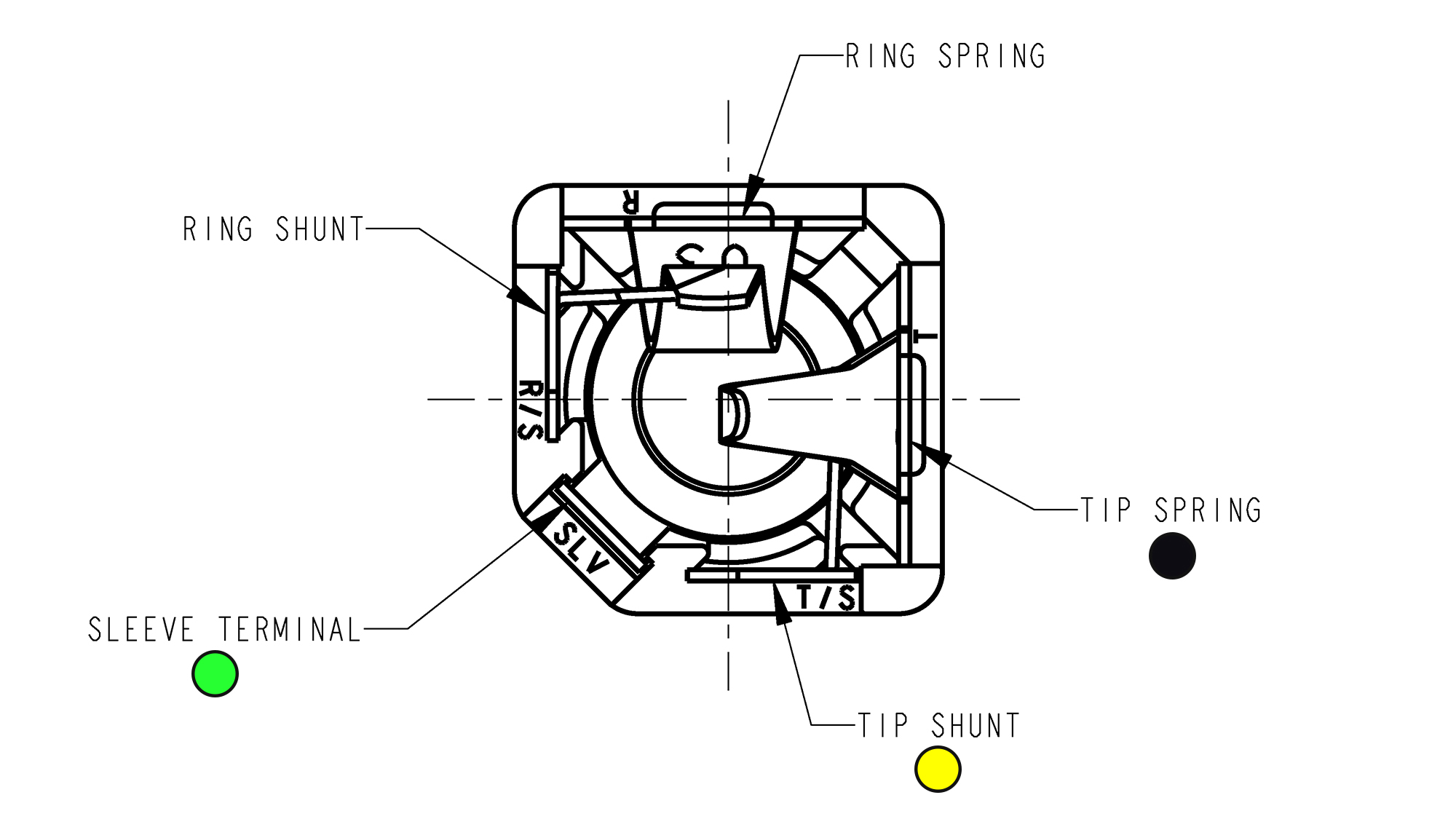
Back of the 1/4″ TS socket, from the datasheet. The three pins along the bottom are required for this project. (Note that this diagram is of the stereo version – the mono plug I have is missing the two top contacts.)
Even though the plug only has two terminals, this jack has three contacts on the back. This is because the pedal is a normally closed (NC) switch, meaning that the two contacts on the connector form an electrical connection that is broken when the pedal is depressed. Because of this, you can’t just create a basic adapter that reads on or off; it’s not possible to distinguish between the pedal being pressed (open connection) and the pedal being unplugged (also an open connection).
This third contact (the “tip shunt”) forms its own little mechanical switch with the tip spring. When the plug is inserted, the shunt contact is pushed away from the spring, breaking the electrical connection. This gives us a logic table for detecting whether the foot pedal is connected and whether it’s pushed:
| Sleeve | Tip Shunt | Tip Spring | |
|---|---|---|---|
| (Disconnected) | - | X | X |
| Released | X | - | X |
| Pushed | - | - | - |
In the table, an ‘X’ indicates that the terminals are electrically connected and a ‘-‘ indicates that the terminal is floating. You can see that the “tip spring” connection is common to both, so this will be our ground.
| Sleeve | Tip Shunt | Tip Spring | |
|---|---|---|---|
| (Disconnected) | HIGH | LOW | LOW |
| Released | LOW | HIGH | LOW |
| Pushed | HIGH | HIGH | LOW |
Here’s the same table with the voltage levels. Both the sleeve and tip shunt connections require pull-up resistors for their floating state. I’m going to use the ones built-into the microcontroller.
Case Design
For the case I wanted to make something that was inline with the cable, something that was fairly slim and could be mistaken for an attenuator or a gender changer.
The 3D printed design is roughly 85 mm by 30 mm square, which is just wide-enough to accommodate the microcontroller and just long enough that the jack can slide into place. The top cover is retained by a single counterbored M3 screw with threads tapped directly into the case plastic. I printed the case out of black ABS on my 3D printer.
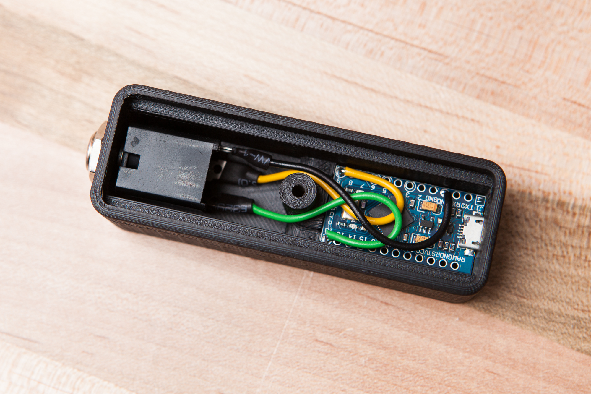
The assembled adapter. The microcontroller is held down with some adhesive and the center support keeps it from sliding backwards.
I soldered some 22 AWG stranded wire to connect the TS jack and the Arduino Pro Micro serving as the brains of the operation. The green wire is the switch detect (“sleeve”), the yellow wire is the connection detect (“tip shunt”), and the black wire is ground (“tip spring”).
These wires loop back on top of the microcontroller to give me a bit of wiggle room for installing the parts. The Pro Micro is held in place using a small adhesive strip. The case design also puts the center bolt support directly behind the microcontroller with a small ledge, which should support it during USB cable connects and disconnects.
Programming
The program on the Pro Micro is pretty barebones. Since the microcontroller is doing nothing except reading the state of the footswitch, the debouncing is done as hard-coded delays: 100 ms checking for cable connection, 50 ms on plug-in, and 2 ms per successive read. I only imagine using this for things like push-to-talk, so a very slight activation delay is preferable to input spamming.
At the moment this footswitch is working with key F23, a virtual function key which isn’t usually used by applications. This allows me to set the footswitch as a hotkey without interfering with any programs or triggering the action accidentally while typing. I’m using the latest version of the Arduino IDE (1.8.5), and as of this writing the included keyboard library does not support these function keys. I’m using the updated version of the library here which supports F13-F24.
As with any virtual keyboard, there are two safety checks at the start that prevent keyboard commands from being executed and enable you to reprogram the board if something goes wrong. Conveniently because of the NC switch, the second of these checks will be triggered automatically if the wires inside of the enclosure come undone.
Here is the sketch, in full:
#include "Keyboard.h"

// User Settings ------------
const char key =  KEY_F23;
// --------------------------
const int connectedPin = 9;
const int buttonPin = 10;
const int ledPin = 17;
// --------------------------

boolean connected = false;

void setup() {
  pinMode(ledPin, OUTPUT);
  TXLED0;  // Disable TX LED

  // Safety check. Ground pin #2 to stop program.
  pinMode(2, INPUT_PULLUP);
  if(!digitalRead(2)){
    failsafe();
  }

  pinMode(connectedPin, INPUT_PULLUP);
  pinMode(buttonPin, INPUT_PULLUP);

  // Safety check #2. Hold button down on startup to stop the program.
  // (Will also trigger if the jack isn't properly connected)
  if(switchConnected() && buttonPressed()){
    failsafe();
  }
  Keyboard.begin();
}

void loop() {
  if(switchConnected()){
    if(!connected){
      delay(50); // Quick debounce
    }
    connected = true;
    readButton();
    delay(2);
  }
  else{
    connected = false;
    delay(100);
  }
}

void readButton(){
  static boolean lastState = false;

  boolean buttonState = buttonPressed();
  if(lastState == buttonState){
    return; // Nothing to see here, folks
  }

  buttonState ? Keyboard.press(key) : Keyboard.release(key);
  lastState = buttonState;
}

boolean switchConnected(){
  return digitalRead(connectedPin);
}

boolean buttonPressed(){
  return digitalRead(buttonPin);
}

void failsafe(){
  const uint16_t blinkTime = 300;

  for(;;){
    digitalWrite(ledPin, HIGH);
    delay(blinkTime);
    digitalWrite(ledPin, LOW);
    delay(blinkTime);
  }
}
Conclusion
This only took a day to throw together, but I was really impressed at how solid everything feels and how well it works. The total cost was ~$5, including the used pedal.
From what I can tell most of the “PC footpedal” products out there seem poorly built or unreliable, so if you’re handy and have access to a 3D printer this might be a good alternative. I’ve uploaded the STL files to Thingiverse if you’re interested in making your own.
This pedal is going to be used for a voice-activated project to enable/disable inputs without touching a keyboard, but I can think of plenty of other crazy uses for it. Stay tuned!
Parts List
Per usual I’ve linked parts throughout the post, but here is a condensed list for convenience:
- 5V Arduino Pro Micro
- Sustain pedal (I found mine at a garage sale)
- 1/4″ TS jack
- 1 M3 bolt
You will also need some adhesive strip to hold down the Arduino and a little bit of wire to make the connections. The type of wire doesn’t particularly matter as this is all low voltage very low current. I used some stranded 22 AWG hook-up wire I had handy.
For full disclosure, note that some of the links above are Amazon referral links that help fund the content on this site. Thank you for your support!