The basic button controls have been added to my Nerf controller, so now it’s time to add a bit of flash: an RGB indicator light and a hidden touch-sensitive button.
This post is part of a series on creating a custom controller for Overwatch using a Nerf revolver. Check out the project page here.
RGB LED
As evidenced by my ambilight project, I’m a firm believer that blinky lights make everything more fun. I wanted to add an external indicator LED for debugging, so why not make it a nice addressable RGB LED? And if I’m going that far, why not integrate it and make it a feature of the Nerf controller?
Separating the Shell
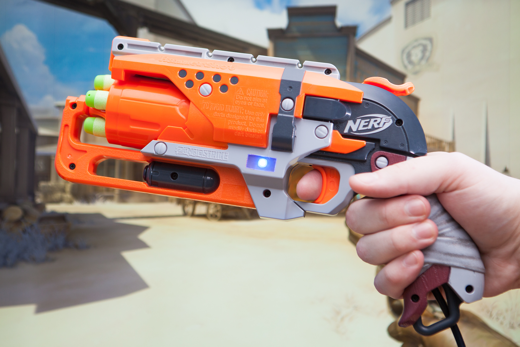
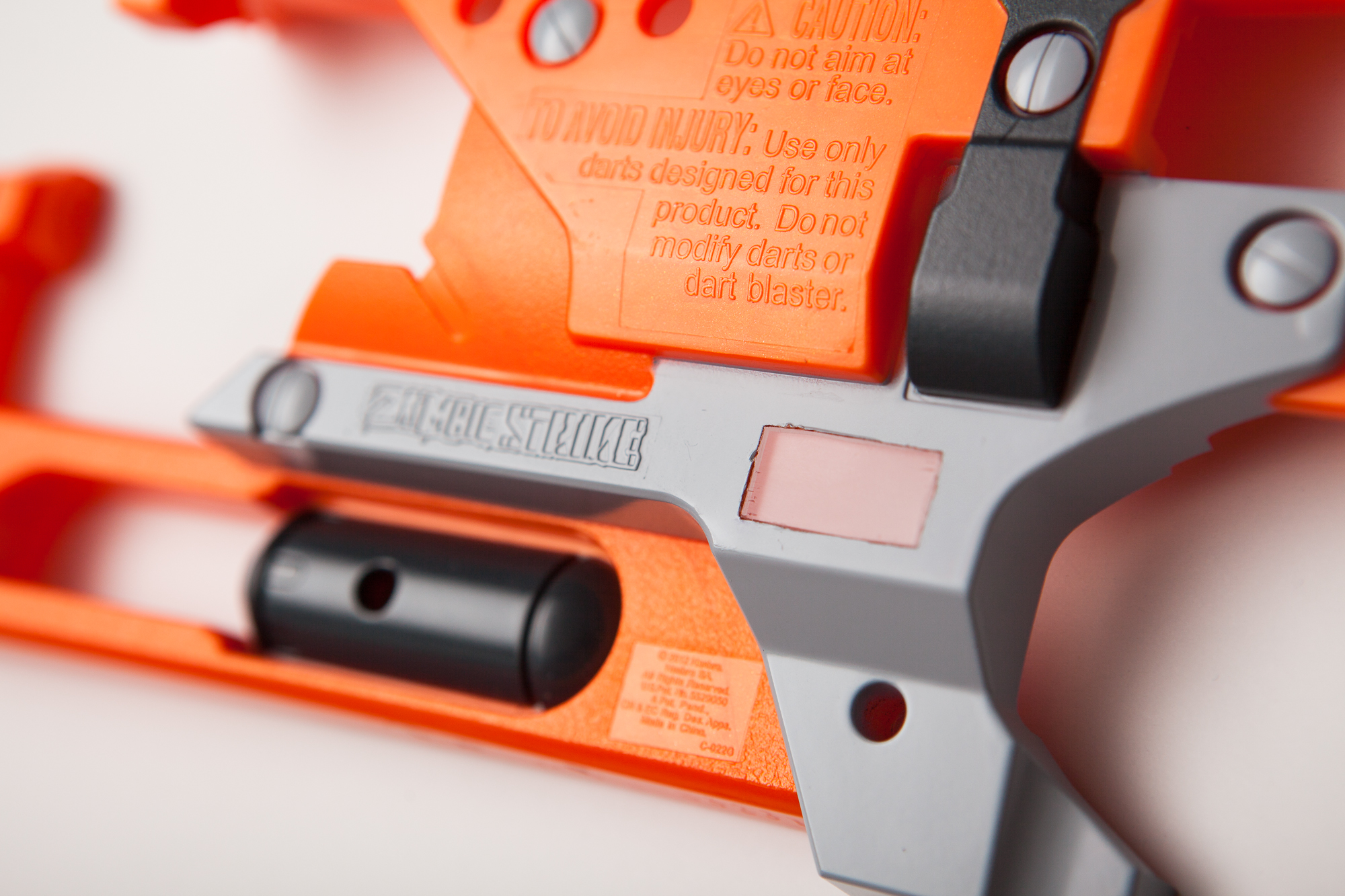
I’m right-handed, so I wanted to add the LED to the left side of the gun so that it’s visible while I’m holding it. The large gray area just to the left of the trigger guard looks like a perfect place for an indicator light.
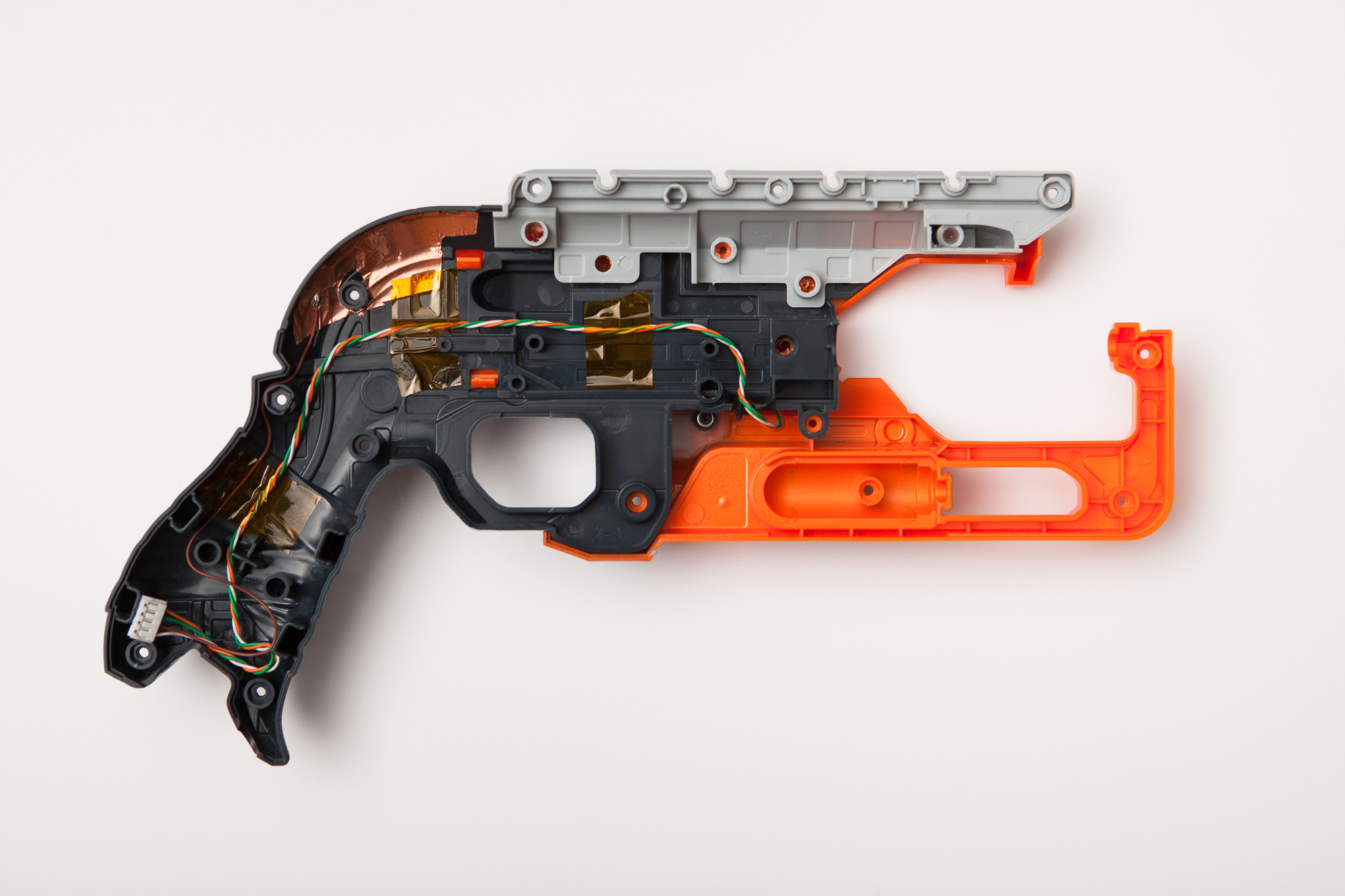
This is a problem though, because the shell of the Nerf gun is actually made out of three separate plastic pieces that are solvent-welded together. I’ll need to separate them to get to where I want the LED to be mounted.


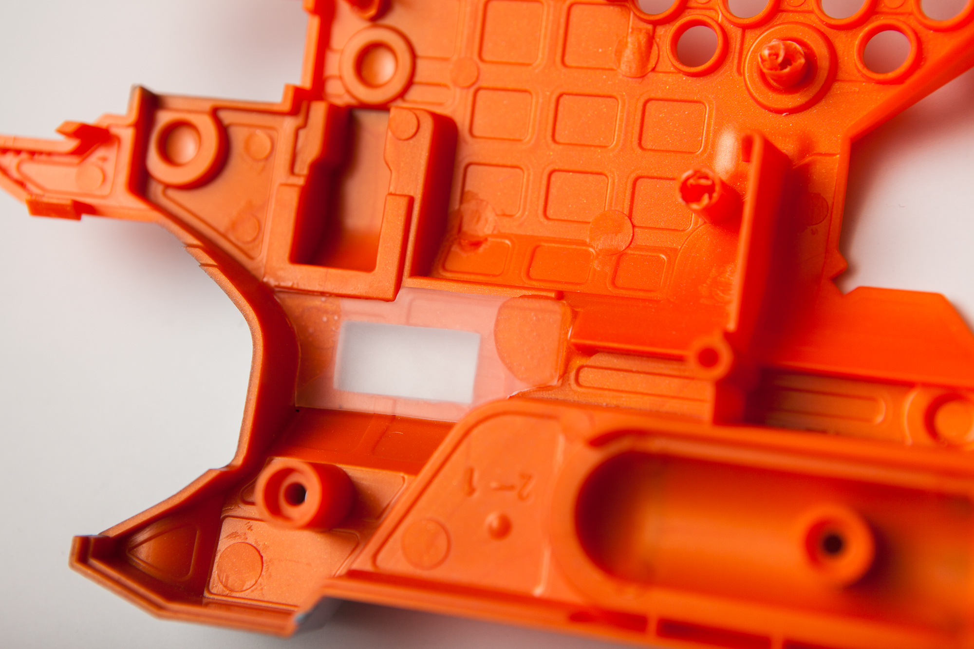
The orange, dark gray, and light gray pieces are all separate injection-molded parts. The three parts are solvent-welded at six points, circled in red. Using an electric drill and a 15/64″ drill bit I very carefully drilled these out, being sure not to punch all the way through. With all of the posts drilled out the light gray piece of the shell popped off with a little bit of force. The orange piece was next, which came off easily after undoing its two retaining tabs. It’s this outermost orange piece that I’ll need to modify to add the LED.
Creating an Opening
I decided on a relatively large rectangular opening, which seemed fitting given the exaggerated style of the gun. I cut out a small piece of paper about 0.75″ x 0.375″ to use as my template and taped it in place with a piece of packaging tape. Using a knife I lightly scored the edges to mark its position.
After removing the template, I laid down some painter’s tape to mark the outline and to try to protect the paint. Then the cutting began.


The initial marks were made with a cutting wheel on a Dremel. This hogged out a lot of material near the center until the tool’s radius because too large. I punched through the thinned wall with a drill bit and then carefully finished the rough cutting with a Dremel cutting bit (1/8″ endmill). The opening was then sized up and squared off with a small needle file, and the masking tape removed.
Window Treatment
I wanted the window to be as flush as I could get it, so I had to cut a piece of clear plastic that could fit inside of the opening.
The completed window attached to the side of the shell.
Using a laminate scoring knife, I cut a piece of clear acrylic from a 0.090″ thick sheet and then carefully sanded it down to size until it was a slight press-fit into the window opening.
To diffuse the window slightly, I wet-sanded the back edge with some 600-grit sandpaper until it was cloudy. After drying it thoroughly I coated the edges with some Elmer’s PVA glue (which dries clear) and pressed it into place. I then left it for 24 hours to dry.
Adding Support
After sleeping on it, I decided that the PVA glue might not be enough to keep the window in place during gameplay. This was confirmed after I was able to easily pull off the acrylic from a test piece I made at the same time.
I didn’t want to glue anything directly to the window’s face, so I decided to add a small piece of clear supporting plastic behind it. If it does fall out, the window at least won’t get stuck inside of the gun.
The supporting piece was cut out of some clear 0.050″ styrene scraps I had, and shaped with both sandpaper and a Dremel. This received the same 600-grit wet sanding on its back face to hopefully diffuse the LED the best I can.
I mixed up some more 5-minute epoxy and attached it with two small dabs. Although I accidentally added a tad bit too much on one side, it luckily didn’t flow over top of the window and cloud it. The support piece is resting directly on the window panel and should make it much more secure.
LED Mounting
Continuing the common theme, I didn’t want to mount the LED in a way that I couldn’t replace it or swap it out if I needed to. This is compounded by the fact that once I re-attach all three parts of the Nerf gun’s shell, I won’t be able to completely see or access the area behind the window.
The solution I came up with was to use a keyed ledge in tandem with a threaded standoff. There is a slight gap when the shell is re-assembled, so I can still undo the bolt and pull the LED out if need-be, without having to undo the entire shell.


To match the curvature of the shell, I traced the outside and then scanned the tracing. After resizing and offsetting for the plastic thickness I had a curve that was close enough to work with. The key size and slot thickness were ballparked based on what the 3D printer could do and the size of the LED bracket. The bolt should be doing most of the work to hold the bracket in place.
The tiny standoff for the bolt has an embedded nut, which avoids needing to cut M2 threads in a tiny 3D printed plastic part. I sized the nut at a slight press fit, and tightening the screw was enough to pull it firmly into the part.
Both parts were printed out of ABS on my 3D printer, which took less than 10 minutes.
LED and Bracket
For the LED itself I’m using one of my WS2812B LEDs leftover from my ambilight project. This isn’t the most-ideal for the controller since writing data requires disabling interrupts, but it’ll do.
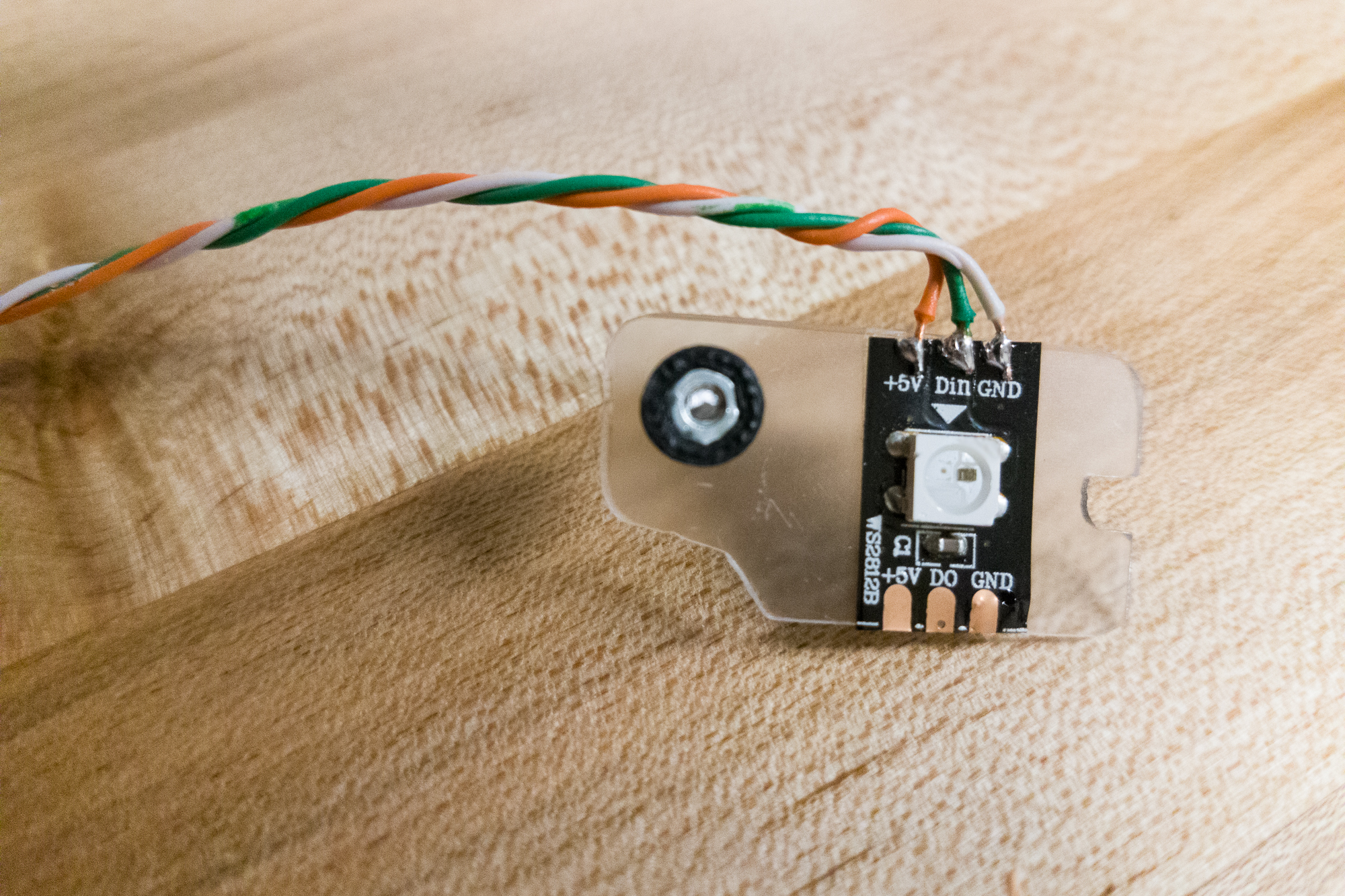
The LED attached to its bracket. You can also see the nut in the 3D-printed standoff. (And forgive the mediocre soldering!)
I cut a mounting bracket out of that 0.050″ clear styrene scrap and contoured it to the geometry of the Nerf shell. After soldering the wires to the LED, I attached it to the bracket with some strong double-sided tape (again, left-over from the ambilight project).
Adhering the LED
With all of the parts made, the next step was to attach them to the shell.
The support piece added behind the window gave me a nice flat area for the adhesive to bond to. I decided to use cyanoacrylate glue (superglue) in place of epoxy, as it’s cleaner and provides a stronger bond for flush surfaces. Although I still needed to make sure the window was properly masked off.
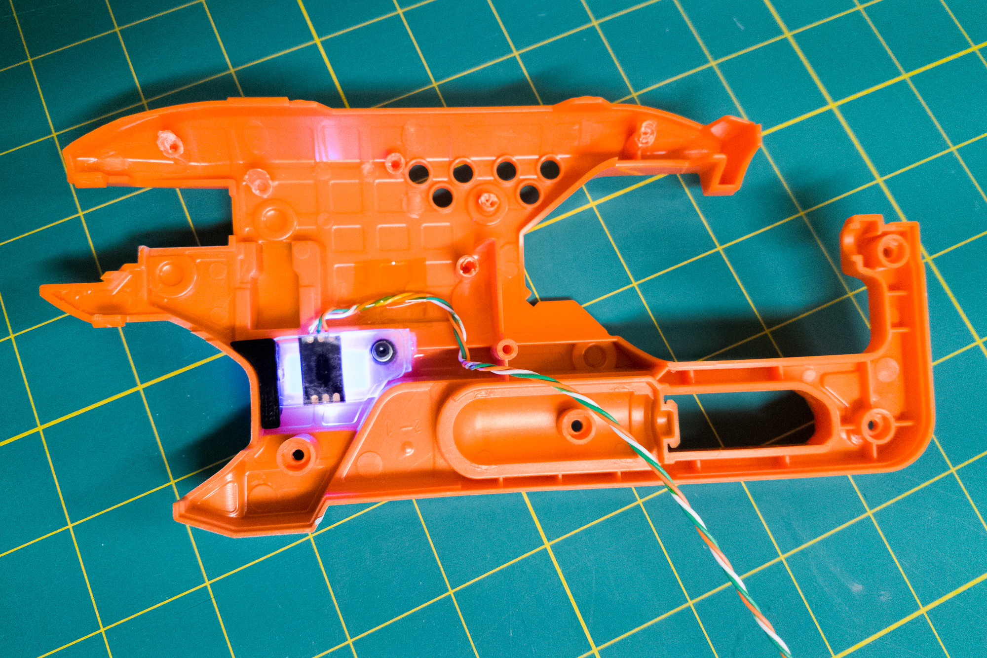
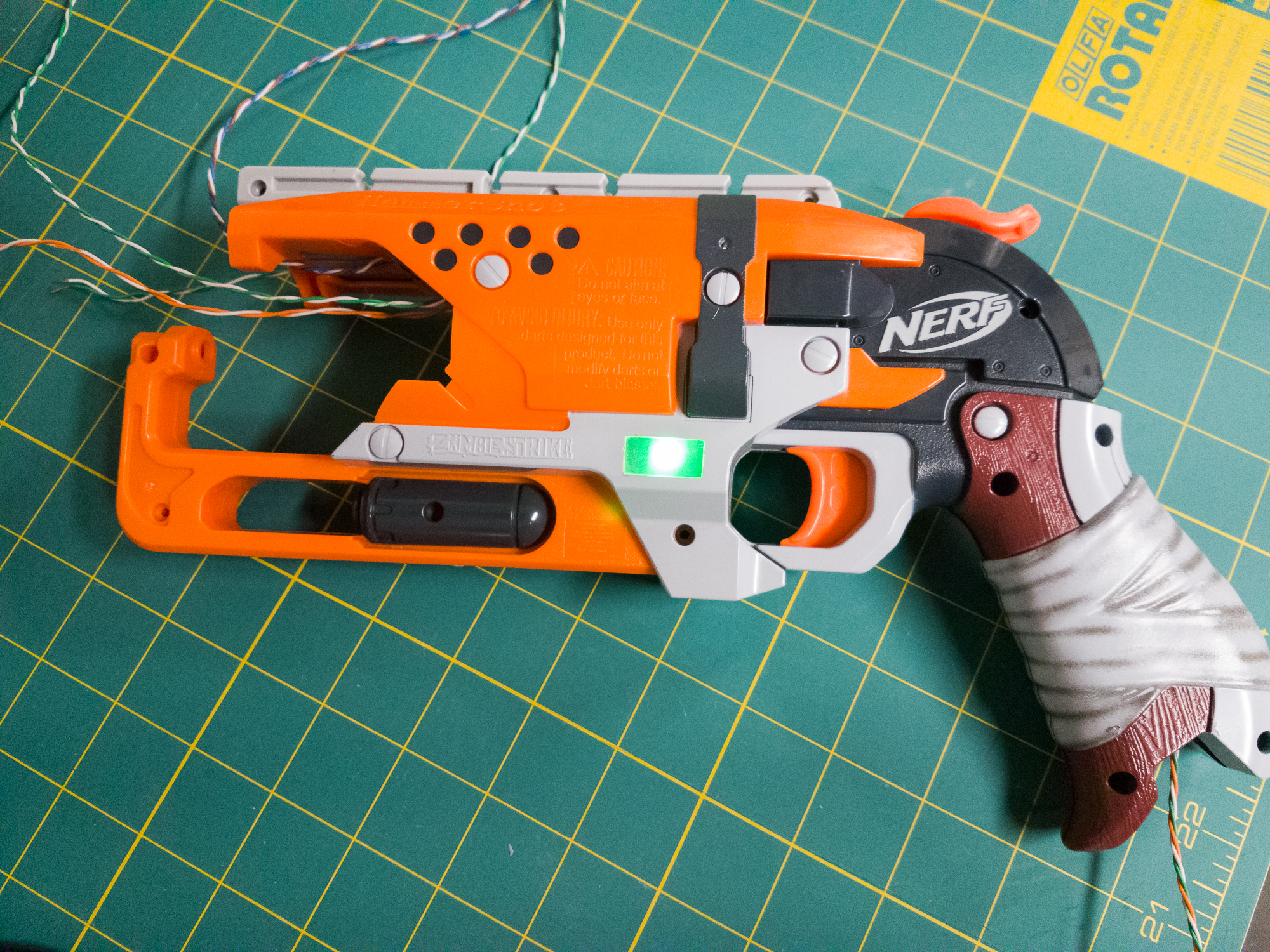
Bright light, bright light!
The ‘ledge’ support was added first. Alignment was easy because it was made to conform to the geometry of the shell. After waiting a few seconds for the glue to set, I added two drops of glue to the other side of the support piece and notched the LED mount into place with the standoff bolted underneath. Then I plugged the leads into an Arduino and admired my handiwork.
Reassembling the Shell
With the LED in place, it was time to reassemble the shell. I still wanted to be able to get it apart if I needed to, so the adhesive of choice was hot glue. I added a few small dabs to the pieces as I was assembling them, and I also filled in the front-most post that I had drilled out. (The retaining clips should hold it at the back.)
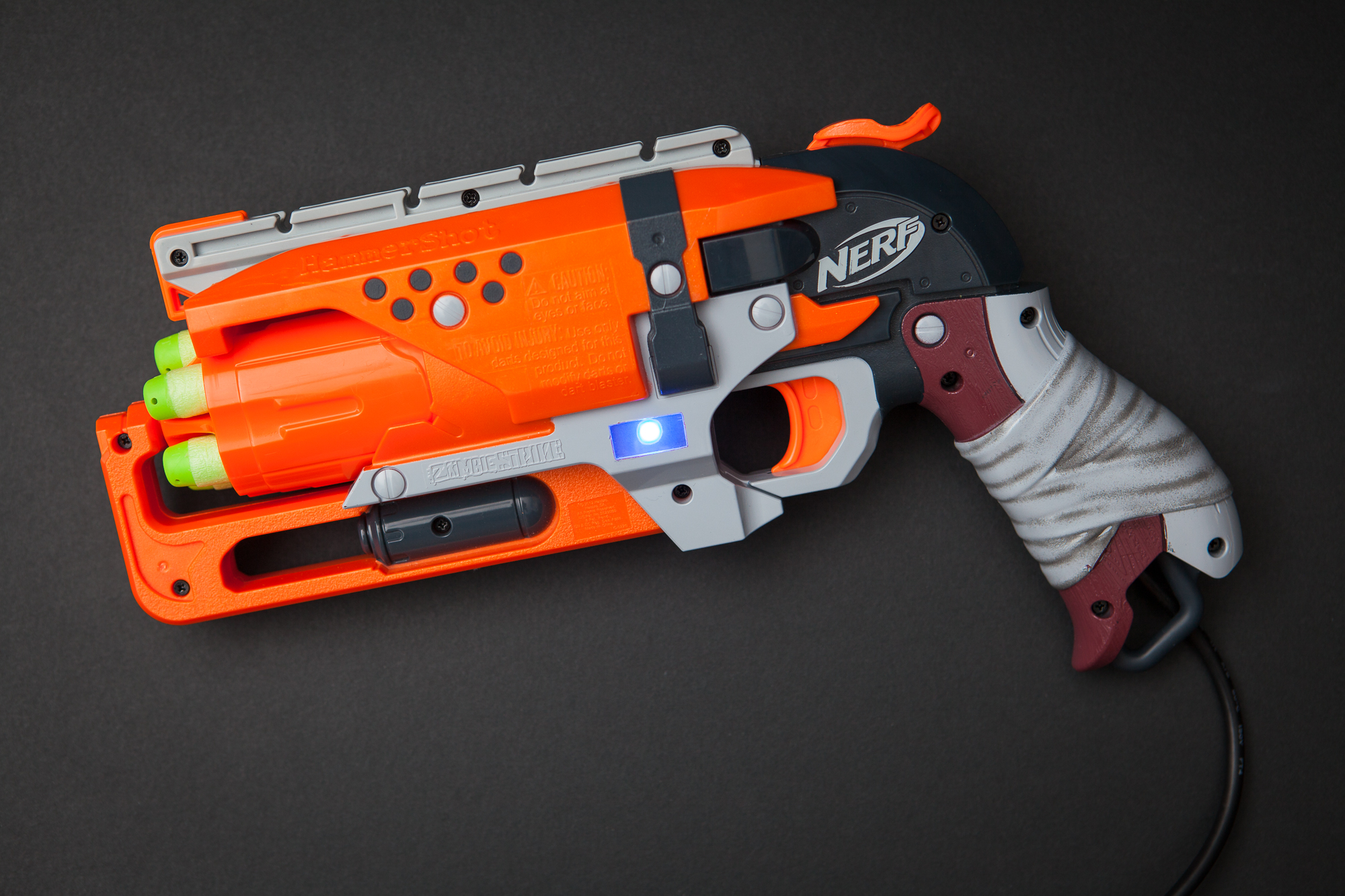
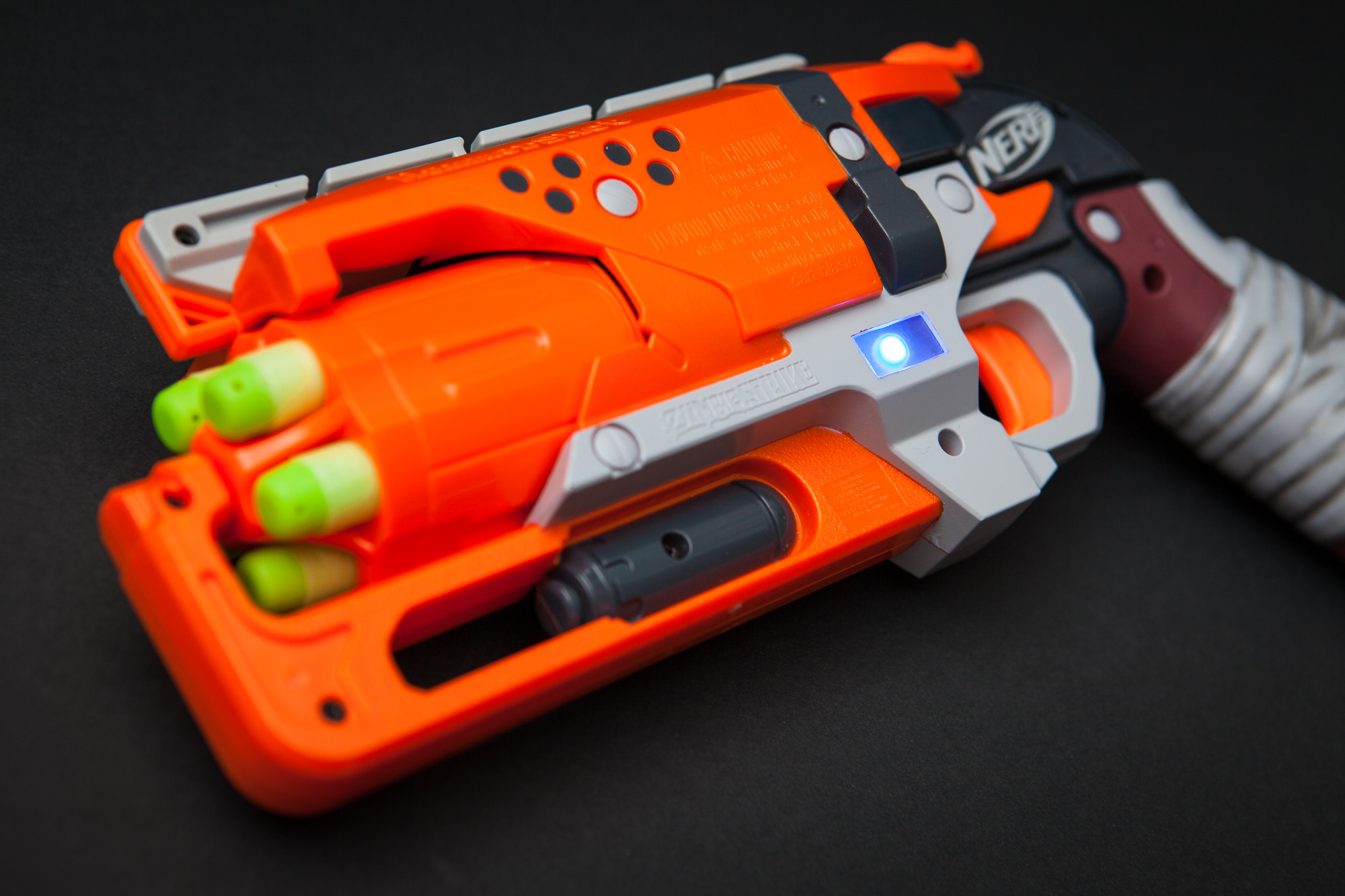
With the shell back together, the LED is done!
Capacitive Touch Sensor
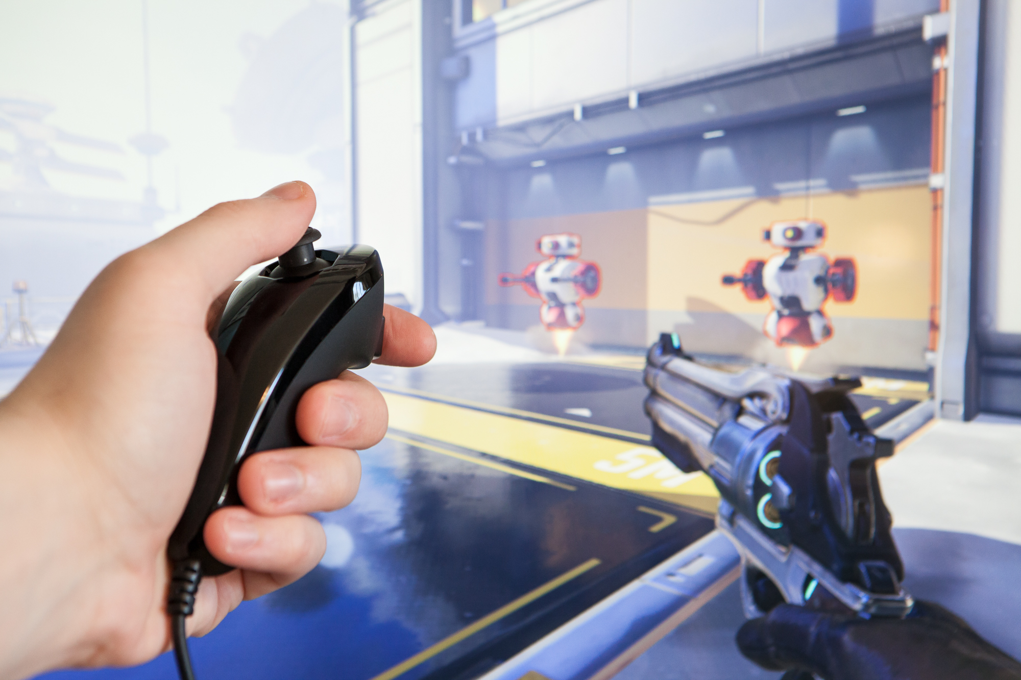
For the controller’s aiming, I’m relying on a gyroscopic sensor. This means the mouse will move depending on how far I rotate the gun.
This presents a problem, though: if I turn the controller to rotate my character all the way around, I will no longer be facing the monitor. Or if I use my ultimate ability and point the controller at the ground, my character will be aiming at the ground. This is no good.
My solution is to add an “override” button. When pressed, the override will disable all of the gyroscope’s mouse inputs. I can trigger the override and then move the controller wherever I want, and when I release it the microcontroller will resume from its new location.
But then a lightbulb went off: how about in place of a physical button, I instead use a capacitive sensor? Faster to use, completely hidden, and more fun to set up. Let’s try it out!
Note: There’s more than one way to make the mouse movement respond to the gyroscope’s output, some of which would still let me turn all the way around. But regardless if I’m using the Y-axis accelerometer to trigger the ultimate I need to be able to disable output at will.
What is capacitive touch?
I only have a cursory understanding of how this works, so please feel free to correct me if I get anything wrong.
Capacitive touch is the technology used on most ‘touch sensitive’ devices. When the human body is insulated from a conductor it forms a simple capacitor. By detecting the size of this capacitance, devices can react to human touch.
According to Wikipedia, this is how it works:
Basically the technique works by charging the unknown capacitance with a known current. (The equation of state for a capacitor is i = C dv/dt. This means that the capacitance equals the current divided by the rate of change of voltage across the capacitor.) The capacitance can be calculated by measuring the charging time required to reach the threshold voltage (of the relaxation oscillator), or equivalently, by measuring the oscillator’s frequency.
In layman’s terms, it’s possible to measure the size of a capacitor, even a very very small one, by providing power and measuring how long it takes for the capacitor to saturate. By lowering the provided power to a very very low current, we can slow the timescale so that even tiny capacitors are filled more slowly than the speed of a microprocessor.
If the capacitance sensed is above a given level, it’s being touched!
CapacitiveSensor.lib
To do this on the Arduino I’m going to be using the CapacitiveSensor library. The library works using two pins attached to each-other through some large resistors (1MΩ+). One of these pins is connected to an antenna, forming a tiny capacitor with the presence of a human hand. The Arduino charges this capacitor and then discharges it through the second pin, measuring the time it takes for the voltage to drop. Moving your hand closer or farther away from the antenna changes the capacitance, which changes the discharge time and can thus be read as an output.
The library can be downloaded from GitHub. Programming will come later – for now I need to figure-out the hardware.
Copper > Aluminum
I’m going to put the sensor just to the left of the hammer, right above the handgrip. This should make it easy to activate with my thumb while I’m holding the gun with my right hand.
I tested the concept briefly by using the CapacitiveSensor library with a small piece of aluminum foil and a taped wire. Even with the aluminum just resting on the inside I could reliably see a difference in the Arduino’s output with my thumb above the antenna. Sensor is a go!
For an antenna material, I ordered some 1″ copper tape from Amazon. I wanted to see if I could get through this entire project with the supplies I had on hand, but this is the one exception.
Although I had some “metal repairing” aluminum tape, aluminum is next-to-impossible to reliably solder to because of its oxidation layer. Copper on the other hand is highly conductive and readily takes solder. A 10 ft. roll of tape only cost me a few dollars, and a soldered wire is going to be much more reliable.
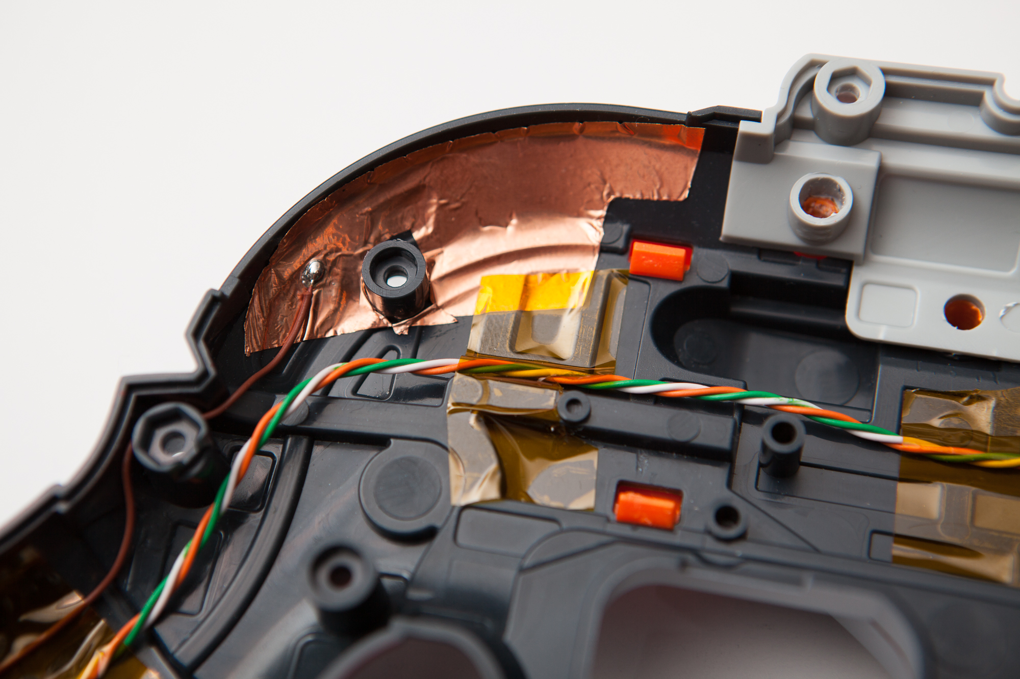
For the permanent antenna, I started by cutting a piece of paper to use as a template. There’s a screw post right in the middle of that area that needs a hole, and I also needed to make a slit on the inside so that the outside edge of the antenna could curve smoothly along the shell. With my template done, I placed it on the back of the copper tape and traced the outline. I used scissors and a craft knife to trim the copper to size, and then soldered on a small wire. After removing the adhesive backing and sticking it in place, the antenna is done!
Stray Capacitance
This project is intentionally a little rough-and-tumble, although I’m trying to still be thorough with my documentation. This capacitive sensor is one of the few places where I can’t be so lax.
When I originally routed the wire for the antenna, I twisted it into a bundle with the rest of the LED wires for packaging – even though I know twisting wires willy-nilly isn’t a great idea. When I went to test the antenna however, the Arduino constantly returned a value indicating that the capacitance was out of range. This was concerning: what was going on?
After some debugging, I realized that this only occurred when the 5V line for the LED was connected. The best that I can tell this is a great example of crosstalk. By coiling the wires I had created my own mini inductor, and the 5V line induced enough current in the sense line that it threw the function out of its range. Uncoiling the wires fixed the problem, and I moved the sense wiring away for good measure.
This highlights a downside to the capacitive sensor: it reacts to capacitance. Any capacitance. I need to be a little careful while building the rest of the circuit.
Conclusion
With the antenna in place, that’s the entire left-side shell done! And if I may say so it’s looking really slick. This is easily the flashiest part of the build, but that doesn’t mean there aren’t exciting things to come!