One of my first thoughts on how to improve Moppy was to drive it directly via MIDI. At the moment, the format of serial messages sent to the drive controller is proprietary and requires using the “MoppyDesk” application on your PC to convert MIDI notes into playable pins and wave periods.
What if we can skip the PC altogether and simply plug a MIDI cable into the floppy drive controller? The goal of this experiment is just to see if this is feasible.
Why MIDI?
If I have eight musical floppy drives running already, you might be asking the question: Why rework the entire setup to run via MIDI rather than using MoppyDesk? I have a few reasons:
1. No host PC
If you set up the drives to run on an embedded system using MIDI, there’s no need for a host computer. You could drive the setup directly from a MIDI device like a digital keyboard.
2. No Moppy Software
As ubiquitous as Java is, controlling the drives with Moppy still requires you to download and compile the MoppyDesk program onto your device of choice. With class-compliant MIDI support, the drives could connect to any device that supports MIDI and start playing with no configuration necessary.
3. Direct Connections
If you can act as a native MIDI device, it also allows you to hook directly into DAW programs such as Ableton. Rather than installing third party software, emulating a MIDI port, compliling and running MoppyDesk, setting all of the parameters, and only then starting to play notes, you can set the drives as MIDI device directly and you’re off to the races!
4. No mandatory reset
This is a smaller issue, but without any other circuitry the Arduino controlling the drives automatically resets on serial connect / disconnect. This causes a hard reset of the drives, which makes an irritating noise.
Stepping Stones
What I’m doing in this post will not accomplish all of this – at least not yet. This is just a first step in the right direction.
Hardware
For this experiment I’m using two microcontrollers: an Arduino Micro and an Arduino Uno. The Micro features an ATmega32U4 microcontroller, which has two available serial ports: its native USB to serial, and an on-board UART. (This is in contrast to the Uno, which has only one serial port that it also uses for USB serial communication.)
I’m using the Micro as a “MIDI to Moppy” conversion board, and the Uno as a dummy Moppy controller. In an actual setup, it’s unlikely that the Moppy driver would have enough overhead to do the math for this, at least not once you start taking into account polyphony.
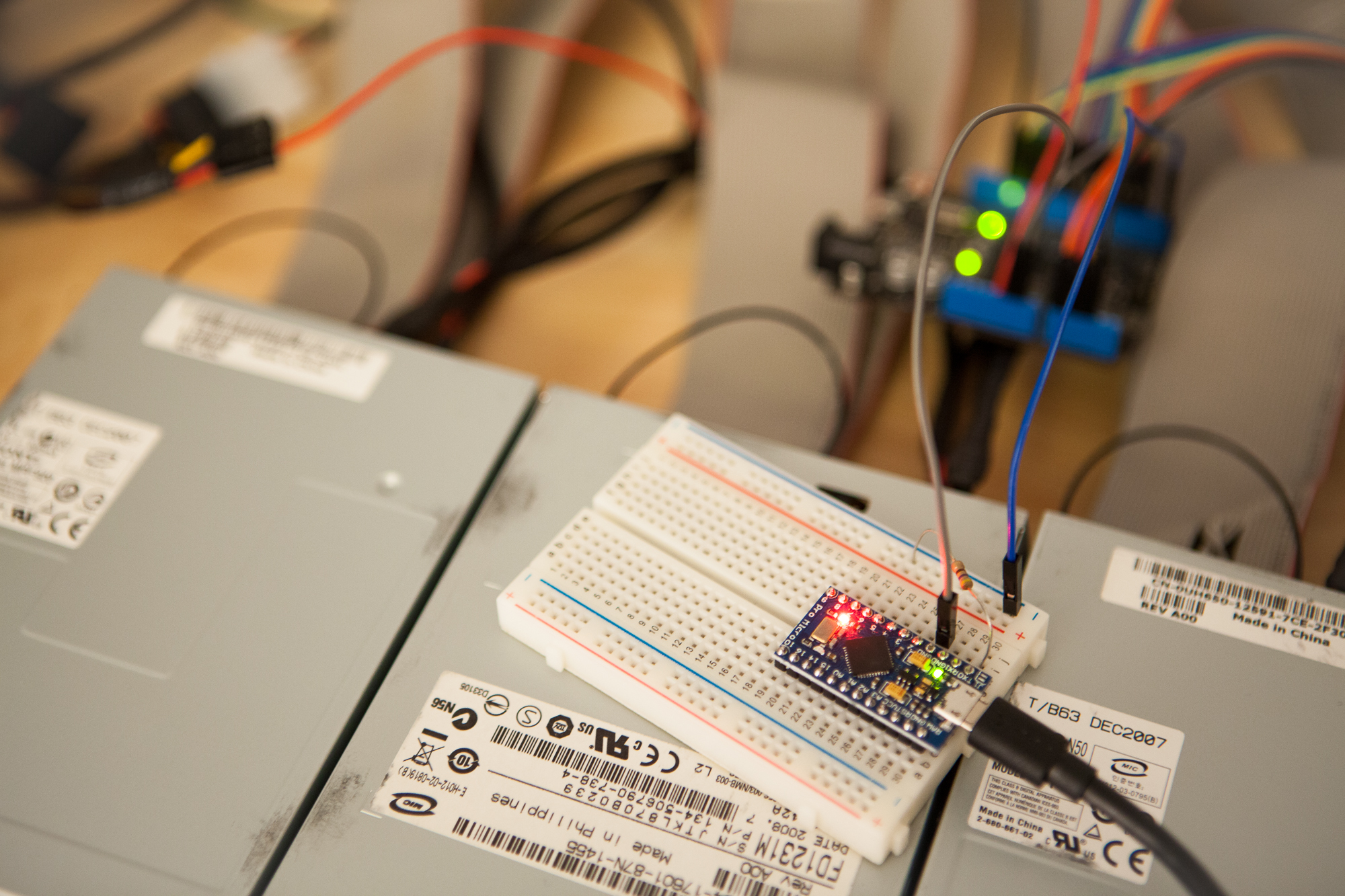
I set the Micro on a solderless breadboard and connected its ‘TX’ pin (#0) to the ‘RX’ pin on the Uno (also, conveniently, pin #0) using a jumper wire.
For the first two tests both boards were connected, via USB, to my PC. For the third test the Uno was powered separately and only connected to the PC via the Micro’s serial line.
An Aside: Native USB
I understand that the Micro has the capability to act as a native USB device, and I could make it act as a native MIDI device rather than using USB to serial. For this experiment though, I wanted to keep the code for the embedded side of things simple.
Arduino Code
Let’s look at the programs running on the Arduinos.
Micro
The code for the Arduino Micro is barebones, although it does do some bit-level math which may be confusing if you’re never seen it before. I’d recommend reading this tutorial on the MIDI protocol.
First, the program checks if a new serial byte is available, and if so it checks if that byte is the start of a MIDI message. If the message is either a “Note On” or “Note Off” message, the program waits for the next two bytes to arrive (note # and velocity), builds a new Moppy-formatted message, and then sends the Moppy message over the second serial port.
The sketch uses a “MIDItoMoppy” library that I’ve been working on in my spare time. The library is intended to convert MIDI notes into the “micro-periods” used by Moppy. It’s still in the early stages (at the moment it’s just a glorified lookup table), but both the ‘getPin()’ and ‘getPeriod()’ functions work – which is all that this program needs.
If you wanted to replicate this without the library, all you would need is an array of the stepper motor pins (corresponding to channels) and an array of the microsecond periods adjusted to the Moppy interrupt resolution you’re using. Look at the MoppyDesk source code for reference.
Here is the Micro’s sketch in its entirety. “Serial” is the USB to serial port, while “Serial1” is the board’s UART, connected to the Uno.
#include "MIDItoMoppy.h"

MIDItoMoppy Moppy;

void setup() {
  Serial.begin(115200);
  Serial1.begin(9600);
}

void loop() {
  if(Serial.available() > 0){
    readMIDI();
  }
}

void readMIDI(){
  uint8_t status = Serial.read();

  if(status & 0x80){ // If status byte
    uint8_t mode     = status & 0xF0;
    uint8_t channel  = status & 0x0F;

    if(mode == 0x90){ // Note on
      while(Serial.available() < 2){}

      uint8_t note     = Serial.read();
      uint8_t velocity = Serial.read();

      sendMoppy(Moppy.getPin(channel + 1), Moppy.getPeriod(note));
    }
    else if(mode == 0x80){ // Note off
      while(Serial.available() < 2){}

      uint8_t note     = Serial.read();
      uint8_t velocity = Serial.read();

      sendMoppy(Moppy.getPin(channel + 1), 0);
    }
  }
}

void sendMoppy(uint8_t pin, uint16_t period){
  Serial1.write(pin);
  Serial1.write(period >> 8 & 0xFF);
  Serial1.write(period & 0xFF);
}
Uno
The Uno code is far simpler. I’m not driving any floppy drives, I just want to see if the Arduino successfully received the serial data.
void setup() {
  Serial.begin(9600);
}

void loop() {
  if(Serial.available() >= 3){
    uint8_t pin = Serial.read();
    uint16_t period = Serial.read() << 8 | Serial.read();

    Serial.print("Pin: ");
    Serial.print(pin);
    Serial.print(" Period: ");
    Serial.print(period);
    Serial.println();
  }
}
This sketch checks to see if 3 bytes have been received, and if so it prints the pin number and the combined 16-bit wave period.
Commence Testing Protocol!
Test #1: One MIDI Packet
Let’s start simple: what happens if we send a custom-formed MIDI packet, the results of which are predictable?
I started by opening the Arduino IDE’s serial monitor for COM7, which is my Arduino Uno. This will show me the received message confirmations.
For this test, I’m using a software called Realterm, which is perfect for debugging serial interfaces.
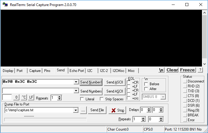
I connected Realterm to the Arduino Micro (COM12 at 115200 baud) and sent the following three bytes, represented in hexadecimal:
0x90 0x3C 0x3C
In MIDI, this is:
- 0x90: Note On for Channel 1
- 0x3C: Note 60 (Middle C)
- 0x3C: Velocity 60
(Note that velocity is ignored by Moppy, but the third byte is needed to complete the MIDI message.)
Immediately, the Uno’s serial monitor popped up with:
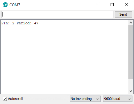
Success!
Test #2: Connecting to a DAW
That was surprisingly easy! Let’s see if we can turn it up a notch. What if we send the Arduino setup some actual MIDI data?
For this test I’m using two pieces of software:
- loopMIDI – Creates a virtual MIDI port
- Hairless MIDI to Serial Bridge – Sends MIDI messages over a generic serial connection
Together, the two allow you to transform MIDI data from musical software into generic serial data for other devices, like an Arduino. Check out this post for more information.
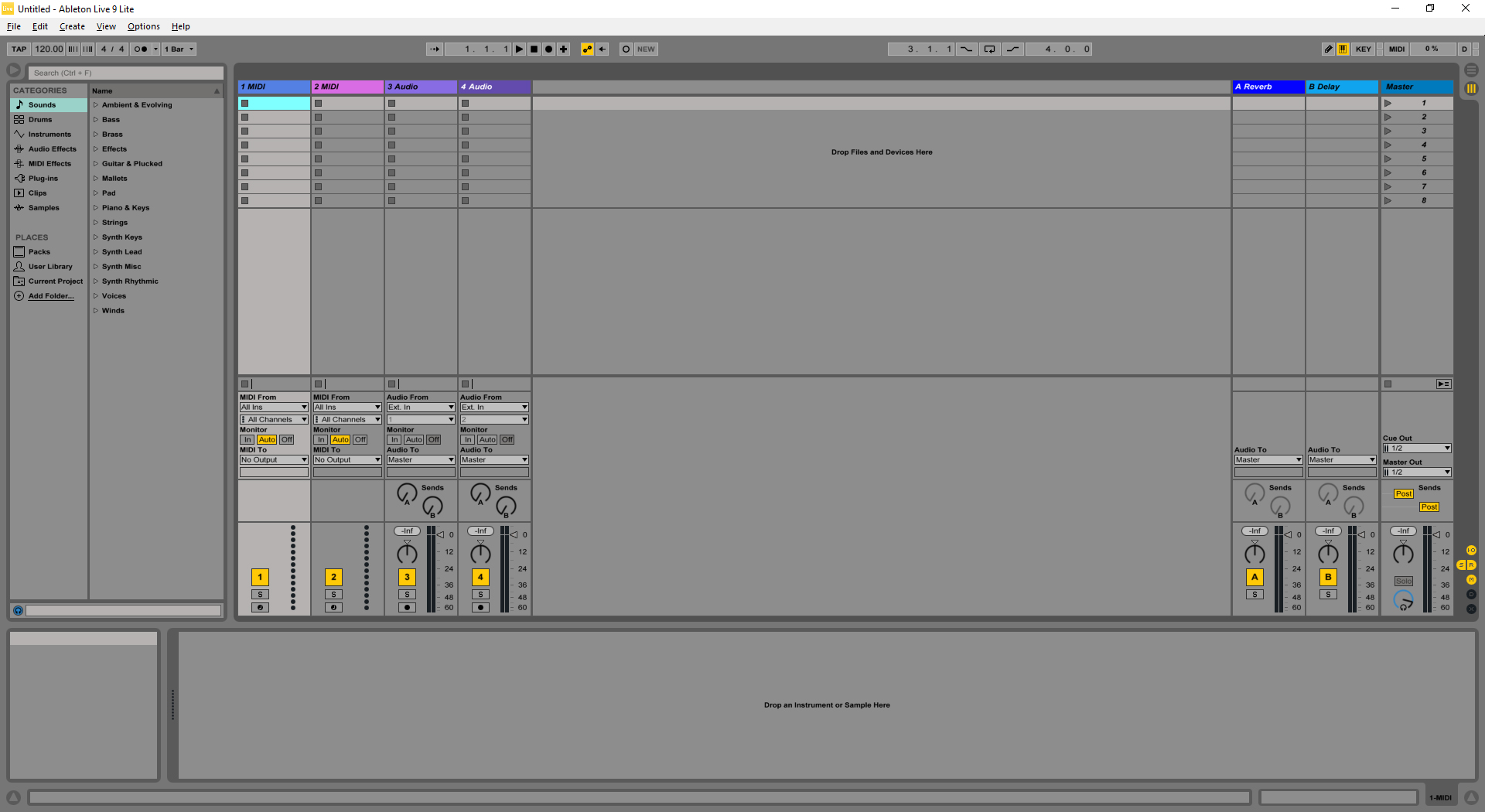
The “Digital Audio Workstation” (DAW) software I’m using is Ableton Live 9 Lite. I started loopMIDI and configured it as an output in Ableton. I then started Hairless and set the MIDI input to loopMIDI and the serial output to the Arduino Micro (COM12). Again, I’m monitoring the output of the Uno (COM7) in the Arduino IDE’s serial monitor.
Note: If you set the DAW to use ‘All MIDI Inputs’, you’ll get the signals you send to loopMIDI back from the loopMIDI input. It’s a loop, get it?
With everything connected, I played a few notes using my desktop keyboard. The result?
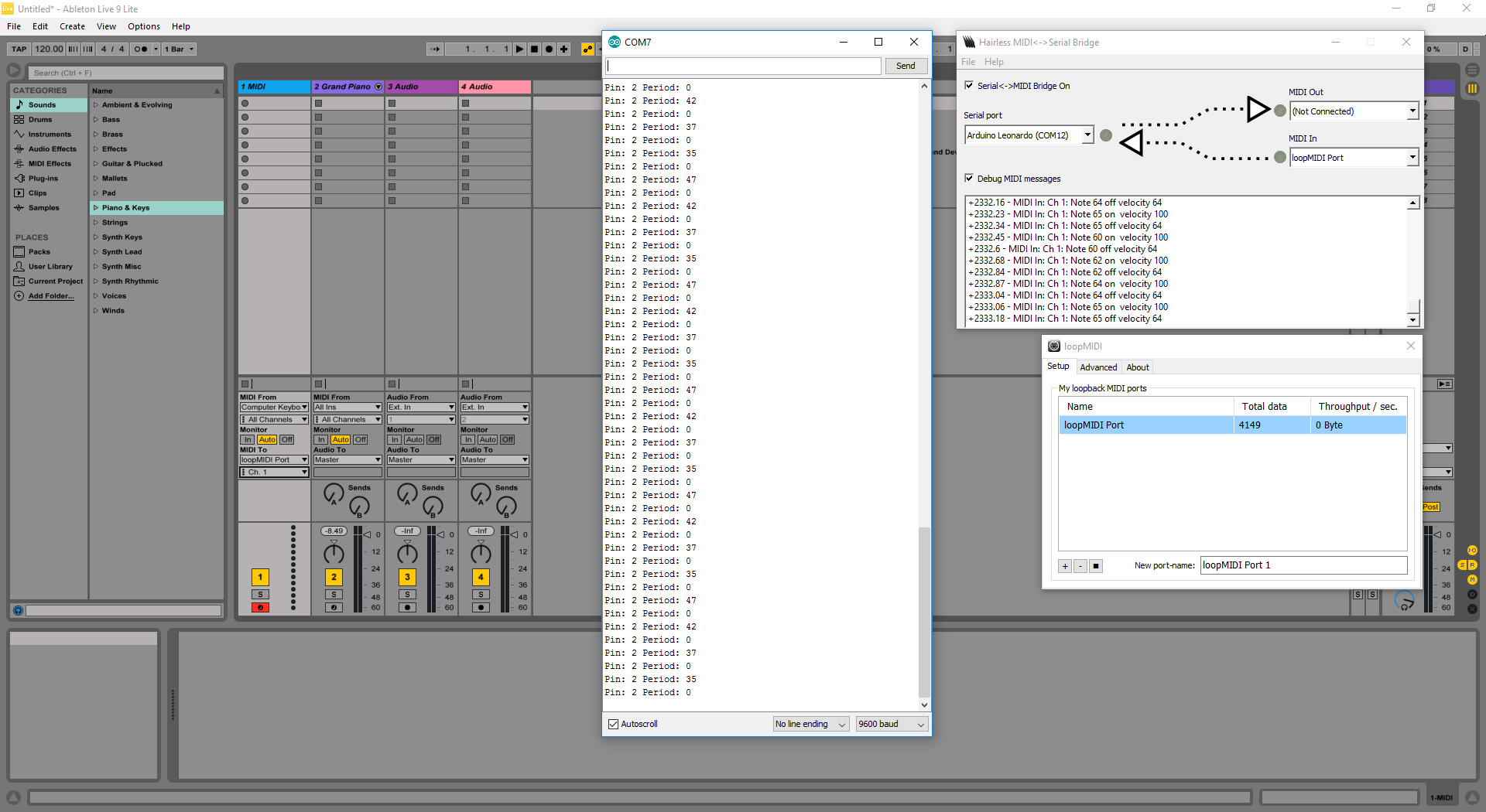
Success again! Changing the MIDI channel in Ableton properly changes the Moppy pin, and note periods look accurate.
Test #3: Connecting to Musical Floppy Drives
Screw it, let’s go all in. The last two tests worked perfectly, so why not plug into the floppy drives themselves and see how it goes?
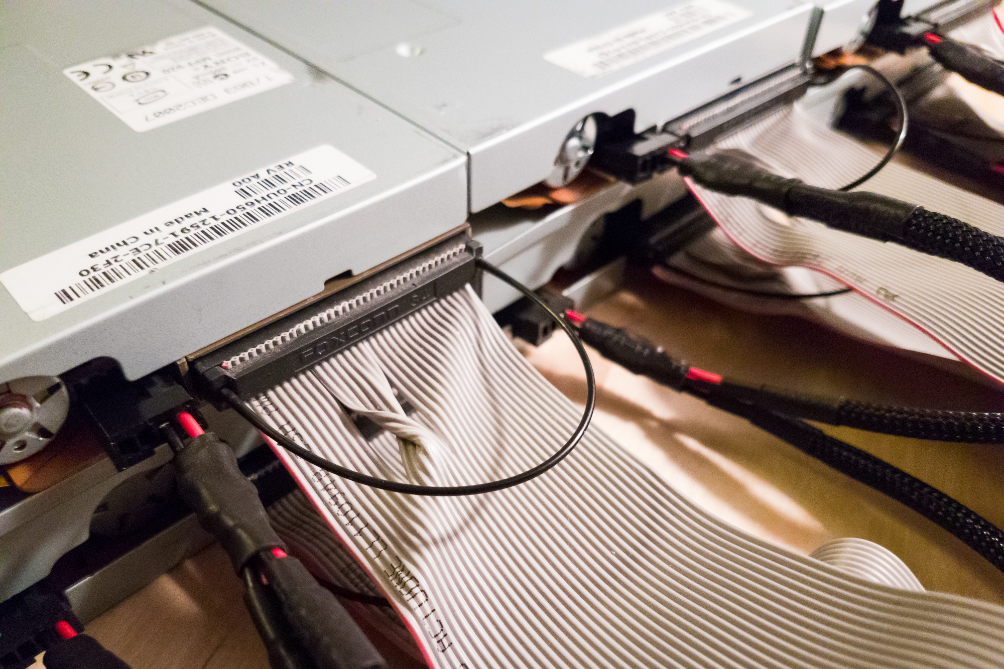
I connected the Micro to the Uno driving the floppy drives in the same way as the test board: ground to ground, Micro TX to Uno RX. I then loaded up loopMIDI, Hairless, and MoppyDesk. Here is the data path:
- MoppyDesk reads a MIDI file and sends properly formatted MIDI data for channels 1 through 8 to a virtual MIDI port created by loopMIDI.
- Hairless takes the MIDI data from loopMIDI and forwards it over a USB serial port to the Arduino Micro.
- The Arduino Micro transforms the MIDI data into properly formatted Moppy data and sends it to the Arduino Uno, driving the floppy drives.
With everything connected and configured I loaded a MIDI file and pressed play. The result?
SUCCESS AGAIN!
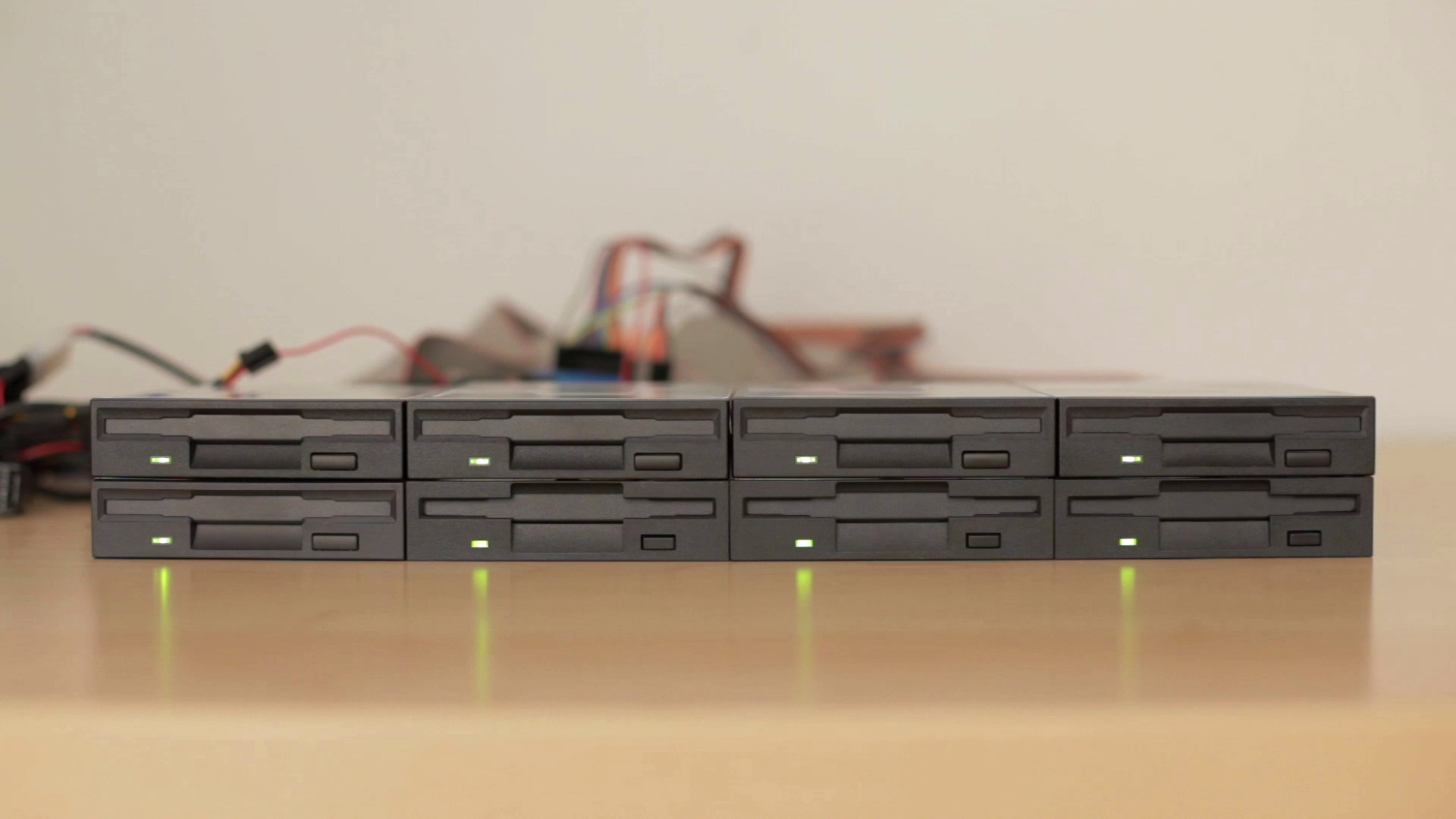
The drives are successfully working over MIDI, with the PC doing no data transformations. The laptop is only being used as the MIDI source – MoppyDesk is not required at all. I also hooked up a MIDI keyboard as a source in Hairless (i.e. no MoppyDesk or loopMIDI) and could play notes successfully.
To my ears, the drives sound identical to the serial-controlled version. I tried out a few other songs, some with more complex note patterns, and I couldn’t hear any anomalies.
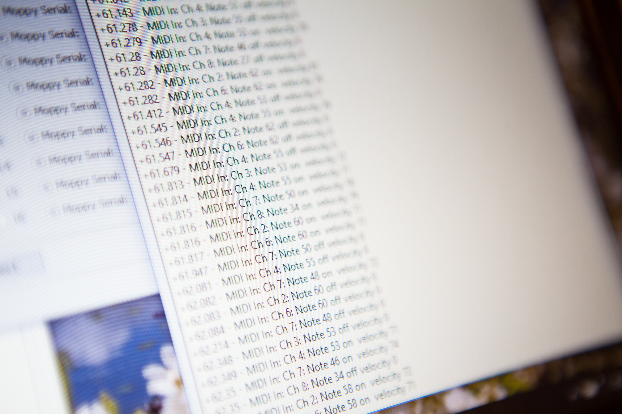
The above gif was made while the drives were once again playing “Cara Mia Addio”. You can vaguely see the MIDI status messages from Hairless scrolling by on the laptop’s screen in the background (the same messages as in the featured image for this post). The red light on the Arduino Micro blinks every time it sends a new packet of Moppy data to the Uno.
Known Limitations
This is mostly a proof of concept that ended up being far more successful than I anticipated. Because of that, I wanted to take a minute to point out a few of the limitations that I’m aware of (and probably even more that I’m not):
Native MIDI
A smaller issue, but one worth mentioning. I’ll need to get the Micro running as a native MIDI device in the near future, to avoid using the additional loopMIDI and Hairless software to do the packet routing.
Out of Range Notes
With the code above, the ‘getPin()’ and ‘getPeriod()’ functions return values of “0” for out of range notes. This mostly means that the slow 9600 baud serial line could potentially be clogged with extraneous data. An easy thing to check for in software, but worth noting nonetheless.
MIDI Message Support
As you can see in the Micro code above, the only messages supported are “Note On” and “Note Off”. Other MIDI messages, such as “mute all” are not, at least in that code, interpreted. So pausing or stopping a MIDI song while a note is playing will cause that note to be continuously played until another MIDI note is sent on that channel.
Blocking Message Loop
This is another smaller issue, but at the moment the “Note On” and “Note Off” modes are blocking while waiting for the full MIDI packet. The downside of this is that if a MIDI message is truncated (e.g. by disconnection), successive bytes will cause junk information to be sent to the Moppy controller.
Polyphony
This is the most significant limitation, and the one that will take the most work to overcome.
With the way the test code is written, the Micro isn’t keeping track of what notes are playing. So if a second note is played on a channel before the first one is muted, the second note will replace the first. More troublesome is that if the first note is then muted, the second note will stop.
The solution to this is to build some software to keep track of notes, but that’s a project for another day.
Conclusion
I’ll call this experiment a rousing success! Everything worked exactly as intended (that is, after I fixed an issue reading two-byte MIDI packets!). It’s not “production-ready” at this stage, but I think with a little work it’s going to be an improvement over the serial version.
I’m hoping to polish up the transformation library and publish it to Github in the near future, so keep an eye out for that and other Moppy improvements still to come.
8 Comments
Emanuel · June 7, 2017 at 12:15 pm
Hi! Great Job!,
I was reading your note and looking for the “MIDItoMoppy.h” library but I can’t find it. Could you post it or send a link where I can get it?
Do you know if the code would work with a MIDI Shield (Sparkfun) connected to an Arduino Mega 2560 with a MIDI Keyboard..?
Thanks!
Emanuel
Dave · June 7, 2017 at 12:33 pm
Hi Emanuel! Thanks for the kind words.
You’re in luck! This post was written with some experimental code, but just last night I got around to publishing the first draft of the “MIDItoMoppy” library on Github. You can find it here: https://github.com/dmadison/MIDItoMoppy. This is still a first draft, so it may have a few bugs that need to be ironed out.
Check out the “HardwareSerial” example, which uses the Arduino MIDI Library. It *should* work out of the box with the Mega and a MIDI shield once you set the proper serial ports, although I don’t have the hardware to test it. Be aware that you’ll only be able to play one note at a time unless you write some code to account for collisions, though.
Let me know if it works for you!
Roel · November 4, 2018 at 12:59 pm
Dear Dave,
Thanks for the supercool Moppy evolution, just what I was looking for. But, I’m not getting it to work. I’m no programmer at all so I think I’m just missing some crucial thing.
So far I made a Moppy setup with two floppydrives and Moppy desktop application, works perfect. But my goal is to make a standalone version with a midiplayer I builded before (midibox/ucapps.de) So my daughters can take it to their primary school and show it, without PC/Moppy desktop. They have a “technical period”
I have an Arduino Leonardo to wich I uploaded the HardwareSerial sketch from your examples. I attached the TX pin from the Leonardo to the RX pin of an Arduino Uno to wich I uploaded the MoppySim sketch.
If I send some midi information to the Leonardo through a MIDIShield and open the serial monitor of the Uno I see the “pin”and period” messages as described. As far as I understand the Leonardo works as it should. It recieves MIDI and translates into “pin and period” messages, but what to do now?
If I upload the standard Moppy sketch into the Uno, it doesn’t seem to react to the signal recieved from the Leonardo. Should it work like this, or am I missing something??? Any help appreciated, I would love to finish this standalone Moppy player!
Cheers,
Roel
Dave · November 4, 2018 at 2:51 pm
Hey Roel!
I’m going to pass the buck and blame SammyIAm for this one. He decided to ditch Moppy and make “Moppy2” rather than continuing with the original repo. Because of that, there’s a bunch of confusion about which “Moppy” is “Moppy”. I raised a few issues on GitHub and got him at least to restore the original repository as “MoppyClassic”, although since he redirected the “Moppy” repository to “Moppy2” all of the hyperlinks in tutorials like mine are broken. He also changed the protocol (for the better, I hope!), which is why my library no longer works.
There is some good news: the code should still work! It just requires that you use the original Moppy (“MoppyClassic”) rather than Moppy2. Now I haven’t messed with Moppy2 at all, so I can’t say whether the quality will be the same. Although from what I remember the pinouts for the Uno should be identical (2/3, 4/5, etc.), making it just a firmware switch.
The other bit of bad news is that this library was never really finished. I jumped ship shortly after to work on the Time Circuits project (which, now that I mention it… is also unfinished. Kind-of a theme there…). There’s no note bend support, and there’s no polyphonic support. But if you can work around that it should do the job fine.
Hope that helps,
Dave
Roel · November 5, 2018 at 5:41 pm
Hi Dave,
Thank you very much for your quick reply and clear answer! I didn’t know about the MoppyClassic version but that solved my problem!
It seems to work fine now. At least I’ve a Leonardo acting as a usb2moppy device and I can play my drives directly from Ableton, and tetris plays as good as it did on Moppy2. And with more drives it’s easy to create polyphony, I like to arrange the notes on different tracks. Now I have to find a nice midi editor that exports multiple midi tracks into one midifile, as Ableton won’t do that..
I’ll give the hardware MIDI shield a try soon, but wanted to thank you and share my succes before! Really cool of you sharing this stuff, without it I surely wouldn’t succeed, Thanx!!!
Roel
Dave · November 5, 2018 at 5:52 pm
That’s great to hear! Glad it’s working for you.
Roel van de Laar · November 18, 2018 at 5:24 pm
Hi Dave, sorry to bother you again but I’m breaking my head again, and just maybe it’s something obvious I’m missing.
I have a Leonardo loaded with the USB-MIDI example from your folder, attached to the Uno loaded with Moppy Classic. Works great. Ableton recognizes the Leonardo as a midi device, and I can play the drives with Abletons midi. But I can’t get the hardware serial to work. I attached the sparkfun midishield to the Leonardo, uploaded the Hardware Serial sketch from your examples to the Leonardo but as I play the drives through a hardware midicable nothing happens.
So I uploaded the MoppySim sketch to the Uno and opened the serial monitor, I got strange messages like
Pin: 0 Period: 57648 Pin: 244 Period: 240 Pin: 96 Period: 57856
Do you have any suggestions? I sent the same midifiles to the Leonardo, over USB and over the hardware port
Best regards,
Roel
Dave · November 19, 2018 at 7:23 am
Hi Roel,
The Hardware Serial sketch is for sending Moppy stream outputs using the hardware serial port, not receiving MIDI over hardware serial. It’s still using the default interface for the input messages, which on the Leonardo is the USB serial. You would need to make a custom MIDI object using the Serial1 bus, and then send the Moppy outputs using software serial. This post has some good information about how to make the custom MIDI object.