For one of my recent projects, I needed a way to control some lights powered by a 120V household wall socket. Rather than reverse-engineering some commercial “smart outlets” for the task, I decided to try and do this the old-fashioned way by embedding relays in electrical boxes.
The Plan
The magic device at the center of these boxes is a relay. A relay is basically an electromagnetic switch, and it allows me to control a large amount of high voltage power (10A at 120V) using a tiny amount of low voltage power (~5 mA at 3.3V). Furthermore, the relay keeps both systems electrically isolated, greatly reducing the likelihood that any high voltage accidentally crosses-over.
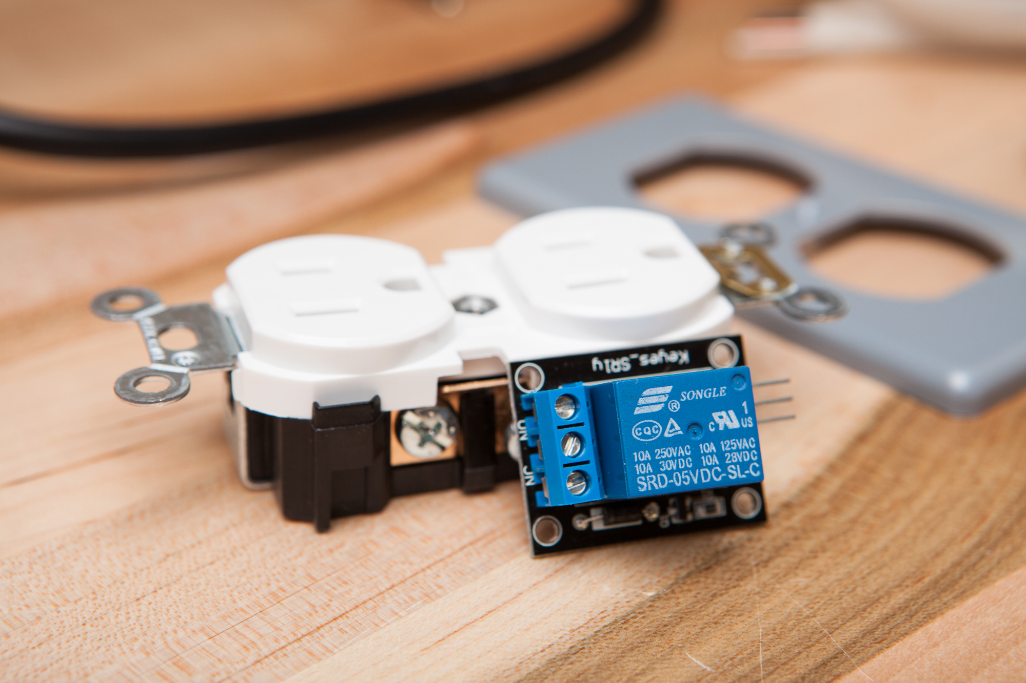
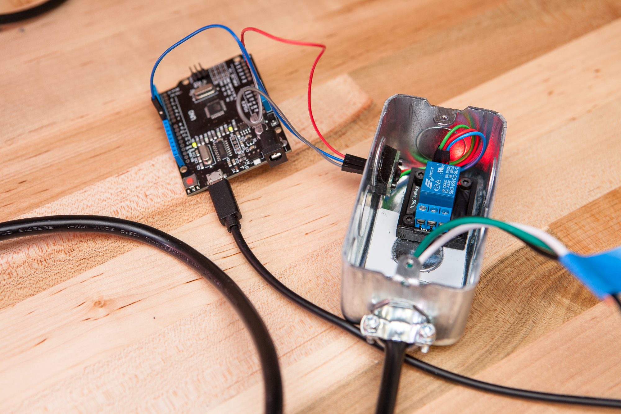
I purchased an inexpensive relay breakout from Amazon, and tested it using an Arduino Uno and a ‘blink’ sketch. While I could have just spliced this relay board into an extension cord, I wanted to build something a bit more robust (and a lot safer). I thought it would be slick to integrate the relay into an electrical box, so I could plug it in and go straight to controlling it without having to tiptoe around exposed wiring.
Disclaimer
Before going any further, I really need to emphasize this: MAINS POWER IS INCREDIBLY DANGEROUS. It is not your friend, and if you are not careful it can and will kill you. Although I believe I’ve done everything I reasonably can to make this safe to use, I am not a certified electrician.
These boxes are being built for a specific purpose, and are going to be used temporarily and in a controlled environment. If you found this post looking for a more permanent solution, I highly recommend looking into WiFi controlled outlets and other “smart home” technology that is UL certified.
I’m writing this post to document what I’ve built. This information has not been vetted and the design has not been certified as safe. If you use any of this information to build your own relay boxes, you do so at your own risk. To that extent I’m not going to provide any of the files for the 3D printed designs I used. I don’t want to be responsible for someone getting hurt.
Electricity is dangerous. Be smart, be safe.
Gathering Materials
With a rough idea of what I wanted, I started looking for building materials.
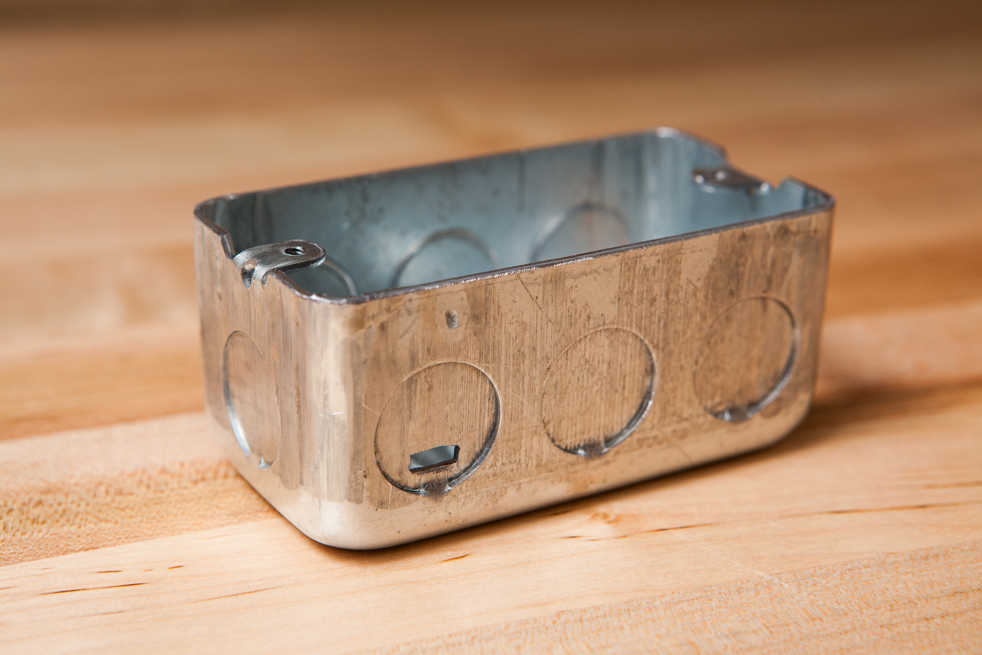
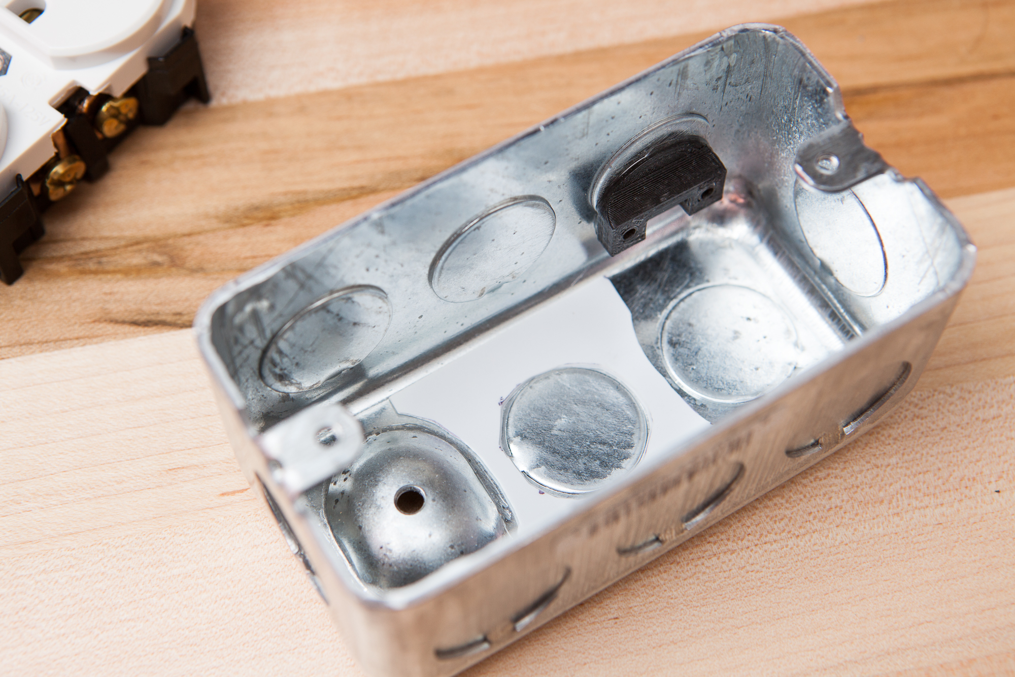
I wanted to keep things small and robust, so I opted for a metal single-gang electrical box (“handy box”). The steel construction should make it more resilient to being knocked around over time, and also provides a grounding path making the whole system safer. If one of the hot wires does somehow make its way loose from the relay board, it should short safely to the box and trip the circuit breaker.
In comparison to a plastic electrical box, the metal box also allows me to use a cable clamp to securely attach the extension cord. It also flexes less, which will make the glued mounts less likely to break off.
I already had the relay board and the microcontroller parts in hand, so the rest of the supplies were just your typical household wiring. I purchased a duplex outlet, a plastic faceplate, and some additional 14-gauge black stranded wire to run from the relay.
After thoroughly deburring the box with a file and some sandpaper, it was time to get to work.
Adding Microcontroller Access
Although this project is designed to switch 120V power, all of the wiring for that is only going to be added at the very end. First, I need to take care of the setup for controlling the relay with a microcontroller.
The relay requires three pins from the microcontroller:
- Signal: 0V – 5V signal for whether the relay is active or not. Active high.
- Power: +5V power.
- Ground: 0V unregulated ground connection.
On the relay breakout, these are provided as three right-angle 0.1″ pitch pins on the back. For safety reasons, I didn’t want male pins sticking out of the box that could potentially be charged with 120V. I’d much rather have a female socket, which is safer and is also less likely to be bent.
The socket I’m using is a basic 3-pin DuPont-style socket that’s non-polarized. I’m using this mostly because I have it on-hand, but its 0.1″ pitch makes it perfect for interfacing with those ubiquitous test jumpers. It would be better to use a polarized connector, but as I’m the only one using these boxes I’m not too concerned.
Making a Mount
I had a number of ideas for how to connect the socket to the box itself, but I eventually settled on this one: a 3D-printed mount in tandem with a piece of perf-board.
I started by cutting a hole in the side of the box for a 3-pin socket connector. It was important to keep this mount low in the box and out of the way of the main receptacle. The hole itself was made by drilling a couple of small holes and then squaring it up using a set of needle files until the socket just barely fit.
The socket’s mount was designed in CAD and printed out of black ABS. The finished mount requires two M2 nuts, which I inserted from the back and pulled into place with the mounting screws. Adding steel nuts here avoids having to cut tiny threads into the plastic.
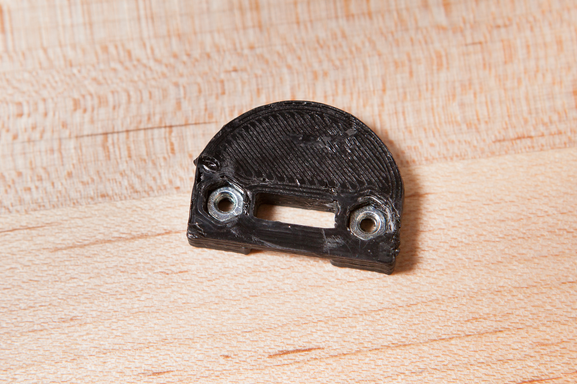
As the back-side of the mount is epoxied to the electrical box, I inserted the screws to depth and added a tiny bit of non-drying plasticine clay. This will protect the nuts while the part is epoxied.
After roughing up the box with 60 grit sandpaper, I used some 5-minute epoxy to attach the mount to the box.
The Perf Connection
With the socket mount in place it was time to build the pigtail. I started by cutting the perf-board to size: 9 holes wide by 3 holes tall. This was done with a pair of straight cut shears, and the edges were cleaned up with a bit of sandpaper. (As always, fiberglass is nasty stuff. Wear a respirator!)
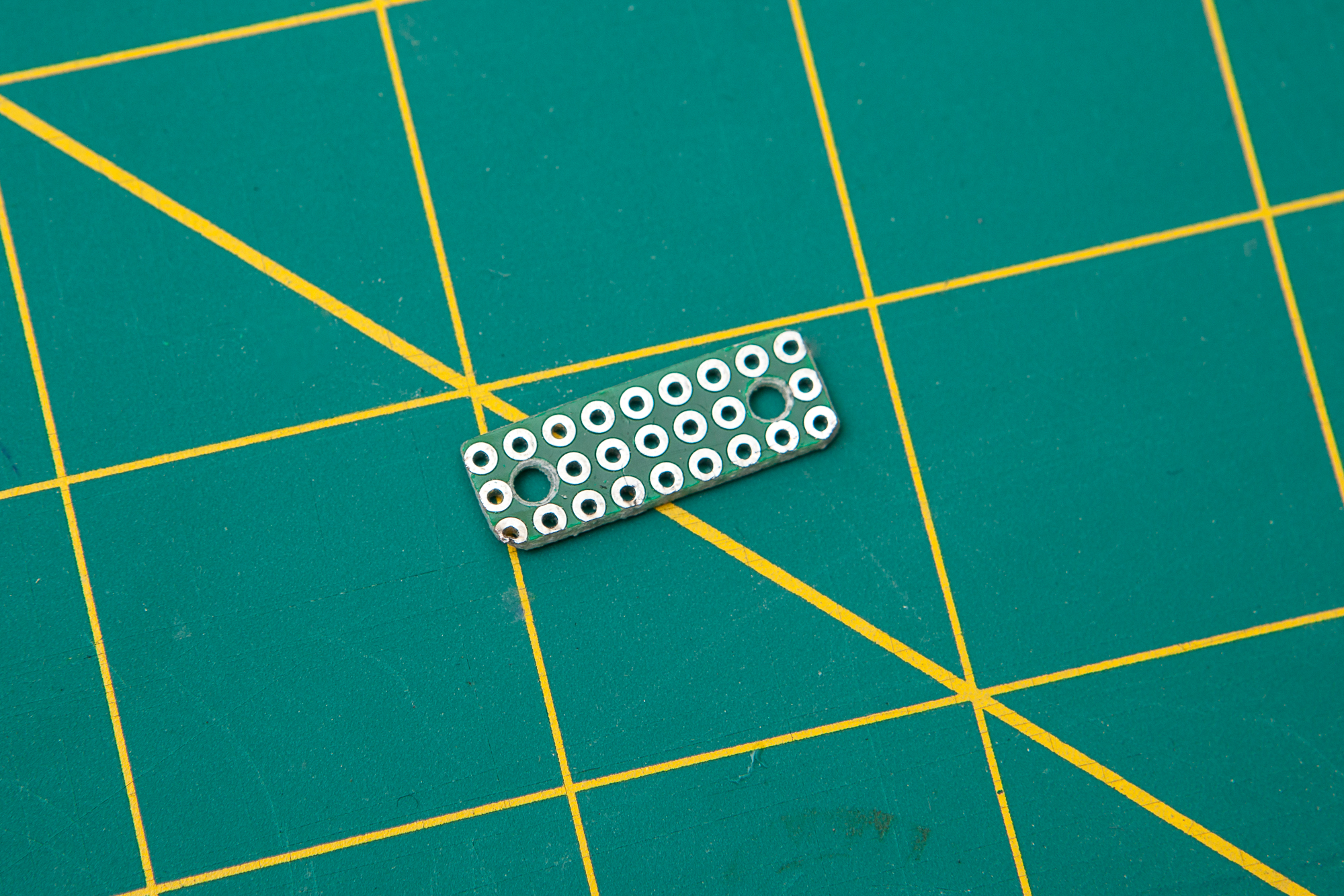
Next, the mounting holes (0.6″ spacing) were drilled out to fit M2 screws, using an electric drill and a 3/32″ bit. The 3-pin socket was soldered to one side, and then three stranded wires were added: entering from the socket side and bending over to touch the soldered pins on the back of the board. These were bridged to the socket pins with a healthy helping of solder.
Using a piece of perf-board here gives me a secure mounting point and allows me to point the connecting wires downwards, saving precious space. It also means that I can replace the entire pigtail if need be – which would not be the case if I had mounted the socket directly to the electrical box. (I like to build things modularly like this. It makes it easy to replace a part if something goes wrong rather than having to start over from scratch.)
Wiring the Pigtail
As this wiring was going to be mixed in with the AC wiring from the extension cord, I had to get a little creative with the color coding. In the U.S. we use black for hot, white for neutral, and green for ground with AC power. Accordingly, I’m using red for +5V, blue for the signal wire, and green for ground.
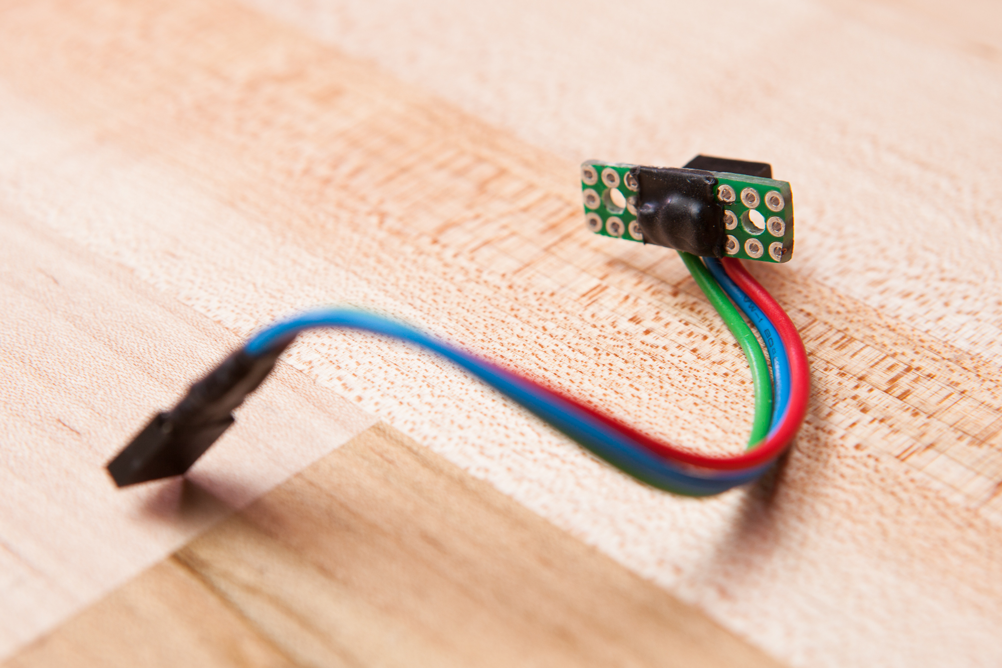
It’s also worth noting that I twisted the wires to change the order for the exposed outside connector. While the pin order on the relay breakout is signal / power / ground, I changed the outside connector to power / signal / ground. This is a more standardized order, or at least the one I’m more familiar with.
After cutting the wires to length I added a matching 3-pin connector to the other side, sans perf-board go-between. This is for connecting to the existing pins on the relay board, which I bent upwards with some pliers to save space. The pigtail was finished with a little bit of heatshrink.
Mounting the Relay
The relay itself is going to live on the base of the electrical box, also in its own custom 3D printed mount. Thankfully the relay breakout already has mounting holes built-in. These are sized for M2.5 bolts, but they’re just big enough to accommodate the M3 bolts I have on-hand.
I printed my custom mount out of black ABS and tapped the holes all the way through. Although I don’t trust the 3D-printed plastic with M2 threads, it seems to hold up fine with tapped M3 threads. Especially with 4 bolts holding down such a light part.
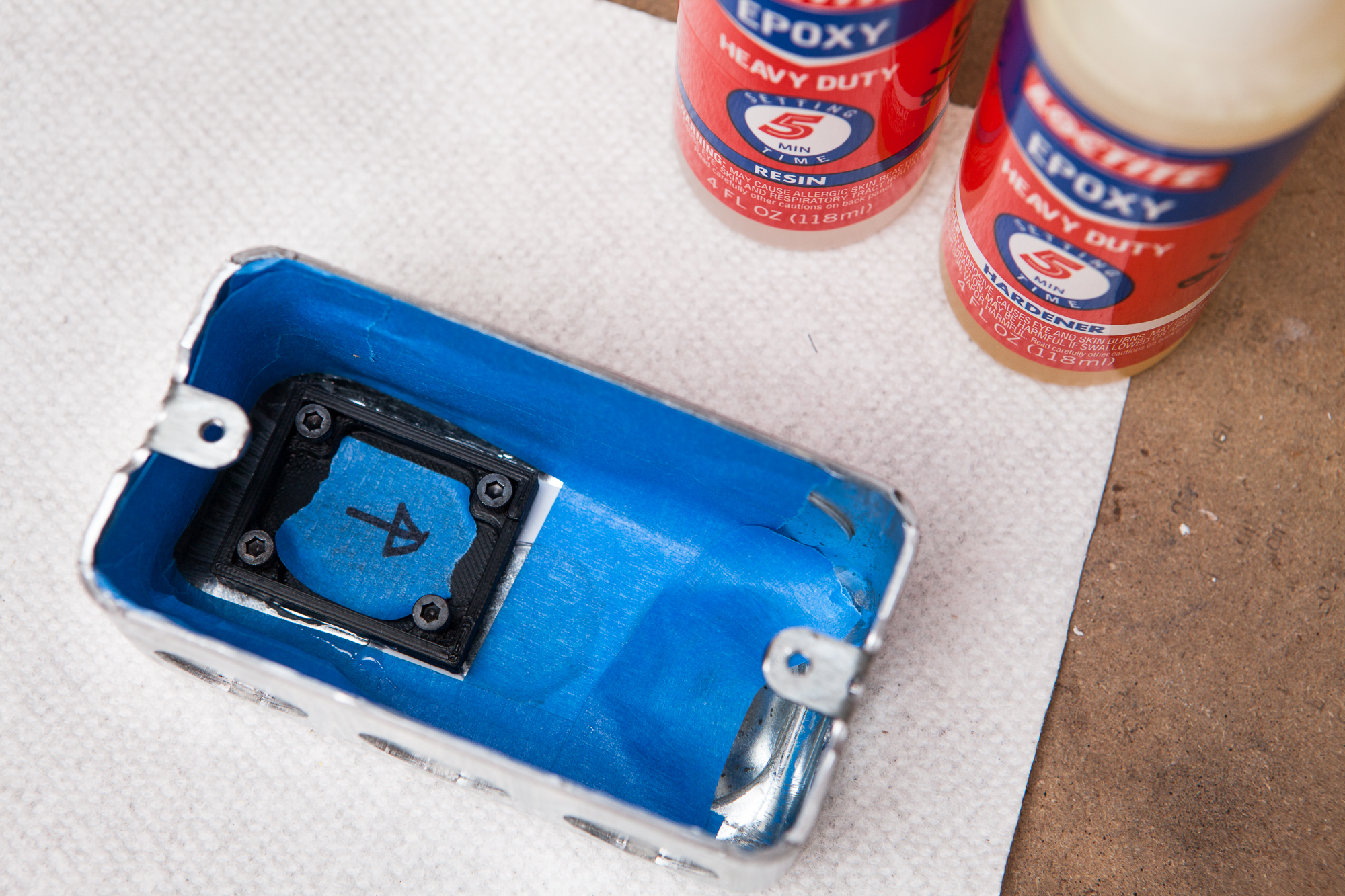
Before epoxying the relay mount to the box, I also added a small piece of 0.030″ white styrene to cover the mounting holes on the back of the box. This was attached with two small pieces of double-sided 3M tape. This is mostly to keep out debris.
Like the 3-pin socket, the space for the mount was prepped with some 60 grit sandpaper and the bolt holes on the underside were covered with a tiny bit of plasticine clay. It was epoxied near the bottom of the box on the left-hand side, just after the rounded edges flatten-out.
With the relay mount attached, I bolted in the 3-pin socket with two M2-6 bolts and attached the relay with 4 M3-5 bolts. Then I tested the relay connection, making sure everything still worked as designed.
Sealing the Low-Voltage Electronics
With the 3-pin socket mounted and the relay in place, I can wrap up the low voltage setup by sealing all of the exposed electronics.
If everything is connected properly and attached securely, this shouldn’t be necessary. But according to the law of our good friend Murphy, doing everything possible to keep the low voltage and high voltage separated will keep this project safe. Never forget: high voltage is dangerous.
To start, I coated the back of the 3-pin perf-board with a healthy coating of liquid electrical tape. I used a full 4 layers, to keep those exposed contacts safely away from prying 120V eyes. After the perf-board was bolted in place I also covered the outside of the connection with several layers of electrical tape.
The relay board itself was easier to seal. The through-hole connections on the left-hand side got a few small pieces of electrical tape, wrapped around the underside of the board. These are pinched by the mount which should hold them securely in place. The underside of the board is completely sealed by the mount itself and doesn’t need additional cover.
The only low voltage component that is still exposed is the SMD LED on the backside of the breakout, which I left exposed as an indicator. This should be safe, as it’s on the back side of the relay and the only AC wire remotely nearby is the AC ground.
Danger, Danger: High Voltage!
The low voltage electronics are finished and assembled in the electrical box. Now it’s time to add the high voltage stuff.
Extension Cord Tail
First up is the wire going from the electrical box to the wall outlet. I initially intended on cutting up an extension cord, but I had some leftover cables from installing new lights in the garage which worked perfectly. These were ~3 feet, stranded, and have a ground wire.
After stripping the sheathing off of the cable, I popped out the top breakout on the electrical box and clamped the cord in place. This left around 6″ of wire sitting in the box for each connection, which is more than plenty.
Wiring Up the Relay
The first AC wires to be set are the black “hot” wires, which provide the 120V current source. These will run through the relay, and by switching the connection to the outlets you can control whether a device receives power.
This relay breakout has its connections through a screw terminal adapter. The center post is the source, the left post is “normally closed” (NC), and the right post is “normally open” (NO). When the relay is unpowered, the source and closed terminals are connected. When the relay is switched, the source and open terminals are connected.
I cut two lengths of black stranded wire (14 AWG) ~ 5″ or so and stripped the ends. These, along with the black wire from the extension cord were lightly twisted and tinned with a thin layer of solder. This solder keeps the strands together and stops them from spreading out when the screw terminals are tightened.
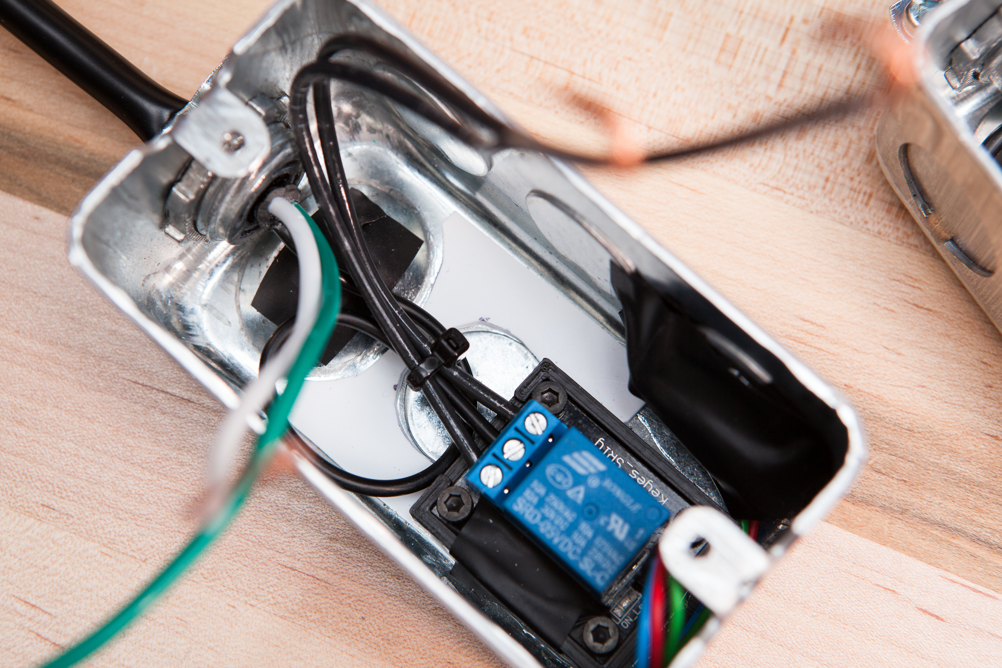
After inserting the respective wires I tightened the screw terminals and gave each one a tug to make sure it was securely in place. I then carefully added a small zip tie around the three hot wires, which should keep them together in-case one somehow comes loose from its screw terminal. To cap things off I added a few layers of electrical tape on top of the screw terminals, just as a precaution.
Outlet Connections
With everything else in place it was time to connect the outlet!
Before anything else, I needed to snap the “duplex” connection between the two hot terminal posts. This allows me to power each outlet separately, and therefore change their behavior. I’m going to keep the top outlet as a “normally closed” (NC) outlet, and have the bottom outlet as a”normally open” (NO) outlet. A pair of side cutters made quick work of this bridge.
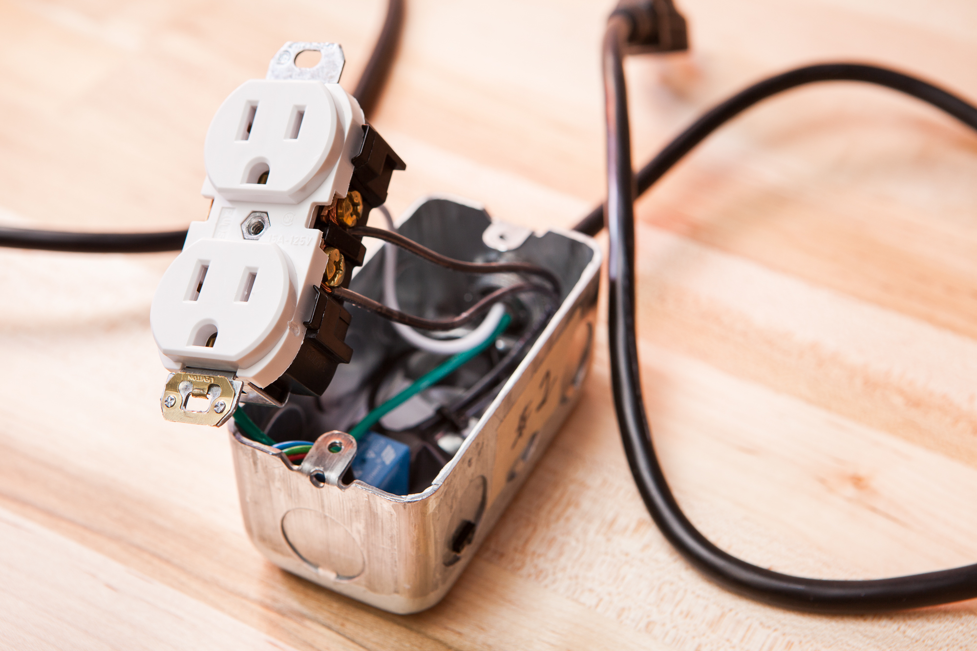
The rest of the wiring was straight-forward: white to silver, green to green, black to brass. All of the wires have plenty of length to pull the outlet out of the enclosure a few inches, while not crossing each-other when sitting assembled in the box. With the wires secured I wrapped the outlet assembly in two layers of electrical tape, just for peace of mind.
You’ll note that I specifically chose not to add an additional grounding pigtail. This is because the source wire from the extension cord is stranded and I was concerned that the outlet screw tightening on two stranded wires would not be as secure. The metal of the box is strongly grounded through the outlet.
With how I designed the relay box, the relay has only 1 mm or so of clearance between it and the back of the outlet. I made sure that nothing was pinched during assembly, but it’s a snug fit for sure!
Testing
Before taking this for a test drive, I did my due diligence to make sure that the connections were solid and nothing was shorted.
I measured continuity between all wires and their endpoints, as well as between all combinations of potential connections including AC to DC. After plugging it in for the first time, I also used an AC circuit tester to triple-check that my connections were correct and that I was switching the hot wire after-all.
(When testing continuity I almost had a heart attack when I measured a very strong connection between the NC hot port and the ground connection. It turns out the extension cord pigtail had wrapped around and the hot fork was touching the outside of the box. The perks of grounding!)
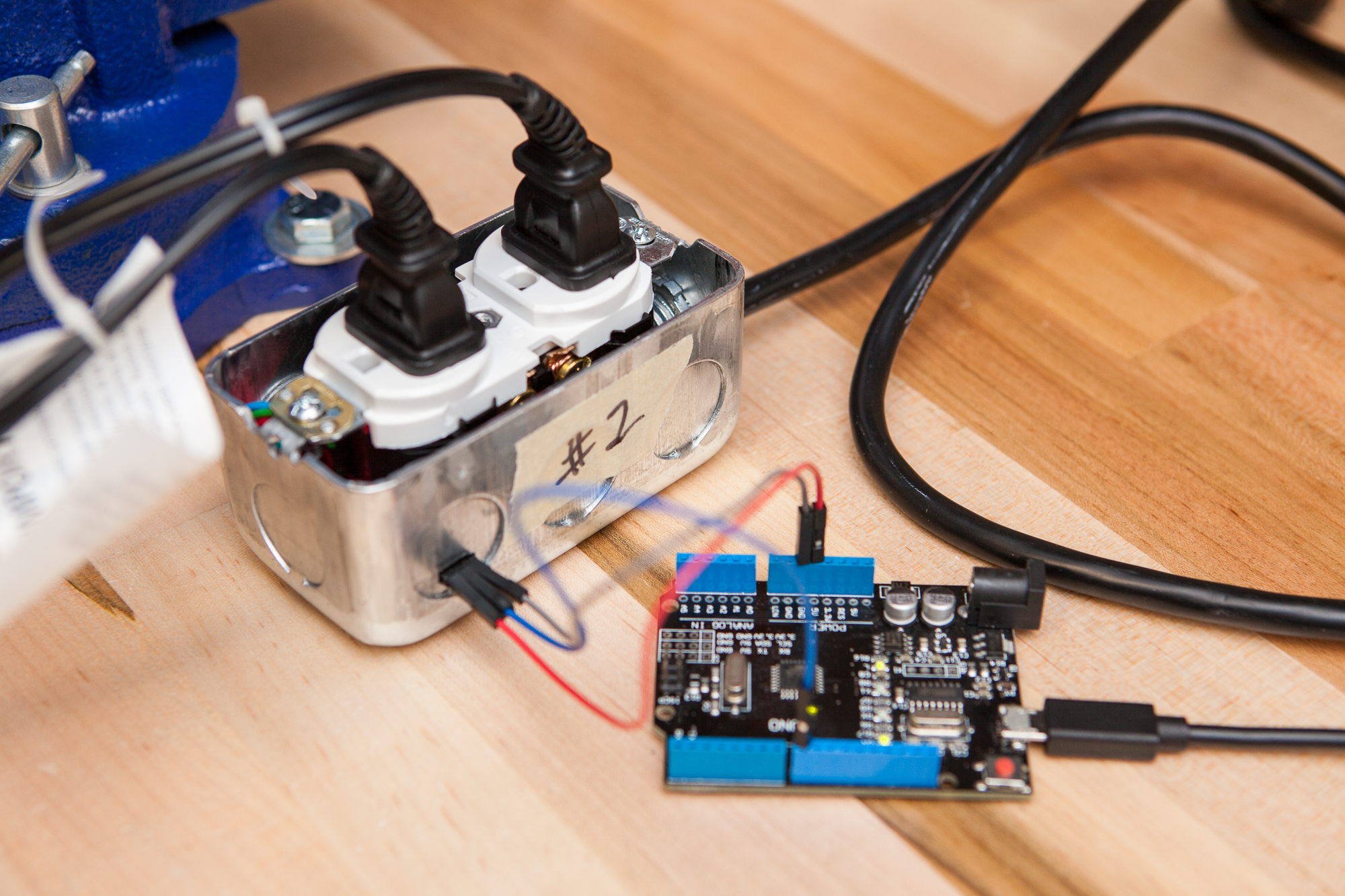
Thankfully all of these tests came out clean and I was able to proceed. I hooked up two 60W equivalent LED light bulbs and watched with glee as they switched back and forth like a railroad crossing. Mission accomplished!
Final Touches
With the electrical components finished, it’s almost time to slap on a faceplate and call this project done. But not before adding a couple of finishing touches, just to give these boxes a bit of polish.
LED Indicator
The relay breakout board I’m using includes a bright red LED that lights up when the relay is switched, and on a whim I thought it would be cool to see this indicator LED through the faceplate.

I drilled a small (1/8″) hole in the corner of the plate above the LED. Behind this, I superglued a small piece of 0.030″ clear styrene as a diffuser. This was wetsanded with 800 grit to give it a slight frosting.
The result is that the red LED is clearly visible from the outside, brightly lighting up to let me know that the bottom outlet is active.
Embossed Labels
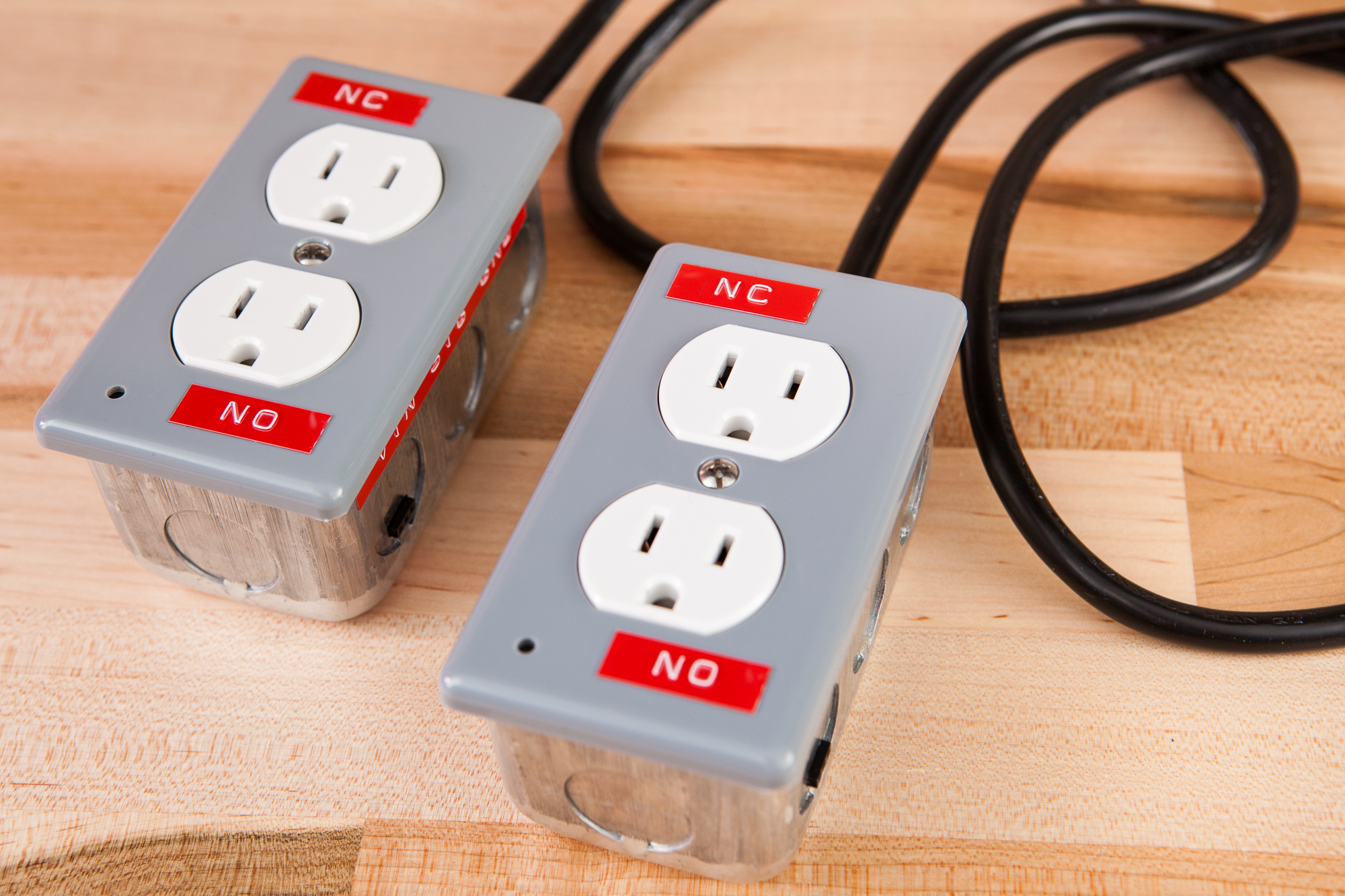
Fully embracing the mad scientist aesthetic, I recently purchased a vintage Dymo embossing labelmaker. So as a final step these boxes got the full labelmaker treatment, in classic white on red:
- The outlets have “NC” and “NO” labels on the faceplate, telling you which outlet is powered when the relay is switched.

- The microcontroller-accessible socket on the side of the box is labeled with “VIN SIG GND”, short for Voltage In, Signal, and Ground.
- Each box has a numbered label along its top edge for identification.

All of the documentation in the world does you no good unless you have it handy. As much as I’d like to think I’ll remember exactly which wire goes where and which outlet is which, it never hurts to have a convenient reference.
Conclusion
The relay boxes are assembled and working! Total cost for each box came out to ~$15, not including the cost of miscellaneous supplies (such as epoxy and electrical tape). Most of that was the price of the outlet ($6) and the relay breakout ($5.80). That makes these cheaper than a commercial solution, but probably not enough cheap enough to justify the time building them or the risks involved with a DIY solution.
Although I did my best to make sure these are as safe as possible, they are definitely only built for temporary use and I’m still going to unplug them before moving them or connecting/disconnecting devices. And even though the relay is rated for 10 A and the the 16 gauge wires for even more than that, I’m also derating the assembly to an absolute max of 5 A for a safety buffer. As confident as I am in the safety of their construction, it doesn’t hurt to be overly cautious.
For the project I have in mind I’m only switching some low-power LED lightbulbs (~ 0.1 A), which means these relay boxes are probably overkill. But they were fun to make, and they’re a useful tool to have in the toolbox. After I finish the project I’m using these for, I’ll be sure to make a follow-up post showing them in action. Until next time!
Parts List
As usual, I’ve tried to do my best to link things throughout the post as I mention them. But just in-case you want the abridged version, here’s a parts list:
Electrical Box:
- Single-gang handy box (1/2″ knockouts)
- Duplex outlet
- Conduit cable clamp
- Plastic faceplate
- 3-prong extension cord (I used a cutoff cable from a light fixture)
Relay + Microcontroller Connection:
For full disclosure, note that some of the links above are Amazon referral links that help fund the content on this site. Thank you for your support!
This list does not include various supplies such as epoxy or plastic sheet, although most of those products I used just because I had them on hand. Again, some of them are linked throughout the post as they’re used.