In my opinion, one of the more novel things you can do with an Arduino is put it to use as a custom game controller for your favorite games. Whether you’re retrofitting a Nerf gun, converting a rhythm controller to play an FPS game, or playing PUBG with a frying pan – using an Arduino makes it quick and easy to build your own custom controller.
In this tutorial, I’m going to show you how to program your own Arduino to emulate an Xbox controller using the ArduinoXInput library.
Getting Started
Hardware
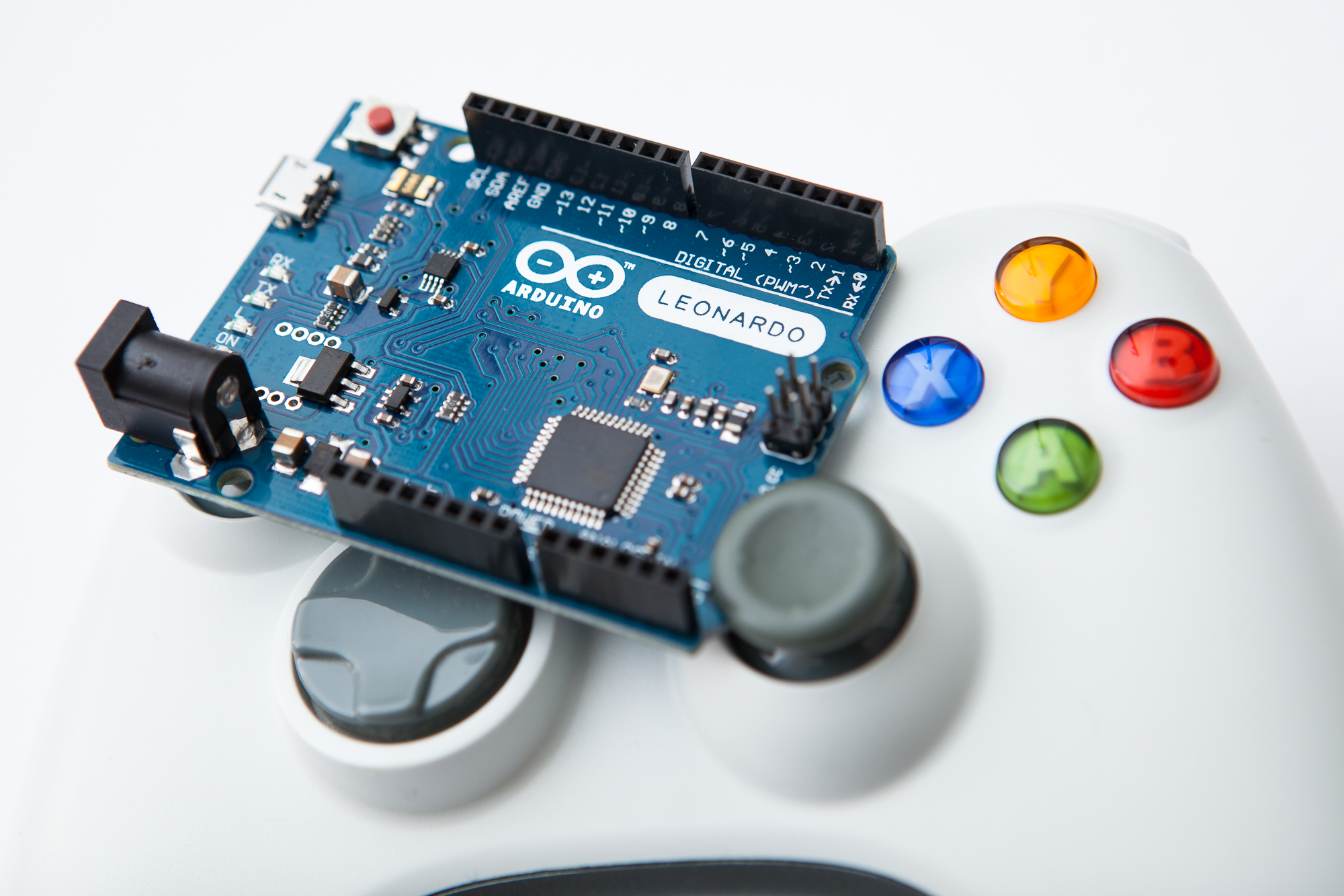
The first thing you’ll need is an Arduino-compatible microcontroller that has native USB support. Supported boards include:
- Arduino Leonardo
- Arduino Micro
- SparkFun MaKey MaKey
- SparkFun Pro Micro
- Teensy 4.0
- Teensy 3.2
- Teensy LC
Using a Leonardo or 5V Pro Micro is my usual suggestion, although if you need a little more ‘oomph’ you can pick up one of the Teensy boards. This is not a complete list however! Check the supported boards list in the library repository to see if your board is compatible.
Note that the Arduino Uno, Nano, and Mega are missing from this list. Those three boards do not have native USB support and will not work for this. You will need to buy another microcontroller. Sorry Charlie 🙁
Software
The next thing you’ll need is the software to make this work. There are two separate but related pieces: the boards package that contains the USB descriptors for the XInput controller, and the library that makes it easy to interact with.
Boards Package
First, you’ll need a copy of the XInput boards package for your specific microcontroller. Because of the way this XInput emulation works it’s not possible to include the USB descriptors with the library – it requires modifying the Arduino core files which means installing some purpose-built boards files.
As of this writing, there are three boards packages available:
- Arduino AVR Boards
- SparkFun AVR Boards (requires the Arduino AVR Boards package)
- Teensy 3 + 4 Boards
You need to download the one(s) required for your microcontroller and install them. Specific installation instructions are provided in each repo. Make sure you have the latest version of the Arduino IDE to avoid any issues.
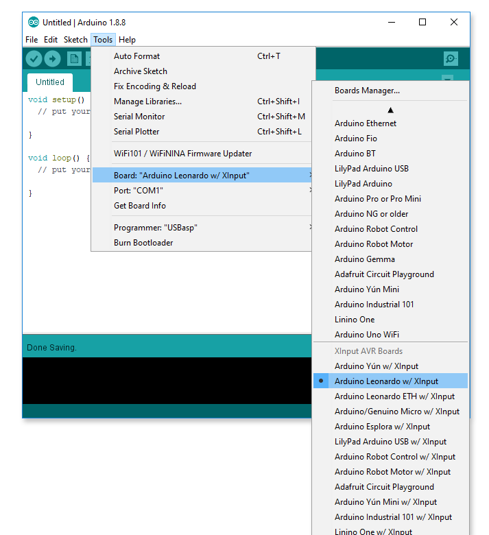
After you have installed the new boards packages, restart your IDE and you should see the new boards available in the ‘Tools’ menu. The AVR boards will have “w / XInput” in their name.
XInput Library
Next, you’ll need a copy of the ArduinoXInput library. You can install this like any other Arduino library – download the latest release as a .zip file and use the IDE’s library manager to install it ( Sketch -> Include Library -> Add .ZIP Library ).
Upload Instructions
A word of warning: as a consequence of using the USB layout of an XInput device, the programmer auto-reset will no longer work. Don’t worry, you can still use the bootloader to program the board! You will just have to reset it by hand when uploading. (This section does not apply if you’re using a Teensy board or a dedicated programmer.)
To do this you need to know where the ‘reset’ button is on your Arduino. If your board does not have a ‘reset’ button, you can wire your own by momentarily connecting the ‘reset’ pin to ground.
To upload a new sketch, connect the board to your computer using a USB cable, and make sure you have the proper board selected in the IDE’s ‘boards’ menu (with or without XInput). If the board already has an XInput sketch on it, you do not need to select a serial port. You should also turn on ‘verbose output’ for uploading in the Arduino IDE’s preferences (File -> Preferences). This makes it easier to time the manual reset and see if the upload succeeded.
To upload to the board:
- Press the ‘Upload’ button in the IDE
- Wait until the status bar says “Uploading…”
- Press the reset button twice, quickly
If you did these steps properly, the board should reset to the bootloader and the upload should begin. AVRDUDE will do its thing and you should see avrdude done. Thank you. near the bottom of the output window. Note that the IDE may say that it “Couldn’t find a Board on the selected port” even if the upload succeeded. This is why it’s important to turn on the verbose uploading output – look for the avrdude message.
Do not upload XInput sketches to your Arduino unless you know how to reset it! Otherwise you will not be able to program it anymore and you’ll have to reflash the bootloader with an external programmer. You’ve been warned…
Hello World
Now it’s time to put this baby to the test. In the IDE’s menu, go to File -> Examples -> XInput and load the “Blink” example. Here’s what it looks like:
#include <XInput.h>

void setup() {
	XInput.begin();
}

void loop() {
	XInput.press(BUTTON_A);
	delay(1000);

	XInput.release(BUTTON_A);
	delay(1000);
}
The example will press and then release the controller’s “A” button every two seconds. It’s a good way to test that the XInput emulation is working properly.
Double check that you have the correct board selected in the “Tools” menu and that you’re using the “w/ XInput” version. Upload the sketch to the board, making sure you follow the uploading instructions above.
On Windows you can test the output by using either the joystick control panel (Run: joy.cpl) or, preferably, a more detailed interface like HTML5 Gamepad Tester. You should see the “A” button (#1) steadily blinking on and off. Success!
Using the Library
“Blinking” buttons is fun, but we’re just scratching the surface with what’s possible. The library gives you access to the following controls available on the Xbox 360 controller:
- 10 + 1 Digital Buttons
- 2 Analog Joysticks (16 bit)
- 2 Analog Triggers (8 bit)
- 1 Four-Way Directional Pad (D-Pad)
In addition to these, you can also read the state of the virtual rumble motors (big and small), and even get the pattern that is running on the LED ring. Let’s jump in!
Setup
To set up the library, you need to include the library header and then call XInput.begin() once in the setup function:
#include <XInput.h>

void setup() {
	XInput.begin();
}
The USB data is automatically handled by the library, although you can choose to handle the output yourself if you want to update a bunch of controls at once:
#include <XInput.h>

void setup() {
	XInput.setAutoSend(false);  // disable automatic output
	XInput.begin();
}

void loop() {
	...  // Update control surfaces here
	XInput.send();  // send data over USB
}
Digital Inputs
Buttons
There are three functions for dealing with the buttons: press(), release(), and setButton():
	XInput.press(BUTTON_A);  // press 'A'
	XInput.release(BUTTON_B);  // release 'B'

	boolean yState = digitalRead(ButtonPin);
	XInput.setButton(BUTTON_X, yState);   // press X conditionally
There are ten buttons on the controller, plus the center ‘Xbox’ button. Here is the list:
BUTTON_LOGO
BUTTON_A
BUTTON_B
BUTTON_X
BUTTON_Y
BUTTON_LB
BUTTON_RB
BUTTON_BACK
BUTTON_START
BUTTON_L3
BUTTON_R3
Pass these values into the button functions above to ‘press’ or ‘release’ the respective buttons.
Directional Pad (D-Pad)
The directional pad inputs function the same as buttons, and you can use the button functions (above) to manipulate them with the following names:
DPAD_UP
DPAD_DOWN
DPAD_LEFT
DPAD_RIGHT
You can also use the setDpad() function to set all four of these at once. The function takes four boolean values, one for each direction: up, down, left, and right:
	// Sample DPAD states
	boolean upPad = true;
	boolean downPad = false;
	boolean leftPad = false;
	boolean rightPad = true;

	XInput.setDpad(upPad, downPad, leftPad, rightPad);
For use with fighting games, this function also includes a simultaneous opposite cardinal directions (SOCD) cleaner to avoid erroneous states (up and down is up, left and right is neutral).
Analog Inputs
Joysticks
There are two joysticks: JOY_LEFT and JOY_RIGHT. Both of these have two axes (XY) and use 16-bit signed values (-32768 is min, 32767 is max, and 0 is centered). The north-east corner of the joystick is positive for both axes.
To set the joystick value, call the setJoystick() function. The first argument is the joystick ID, the second is the ‘x’ position, and the third is the ‘y’ position:
	// Center the left joystick
	XInput.setJoystick(JOY_LEFT, 0, 0);

	// Push the right joystick all the way to the right
	// and slightly down
	XInput.setJoystick(JOY_RIGHT, 32767, -2000);
As of version 1.1.0 there is also a function to set the joystick using four digital inputs (like a direction pad), for use with arcade joysticks that use micro switches instead of potentiometers:
	// Sample arcade joystick inputs
	boolean stickUp = false;
	boolean stickDown = true;
	boolean stickLeft = false;
	boolean stickRight = true;

	XInput.setJoystick(JOY_LEFT, stickUp, stickDown, stickLeft, stickRight);
Version 1.2.0 also adds functions to manipulate the joystick axes separately, in case you’re mapping independent potentiometers (e.g. for a racing wheel) or other types of inputs. Prior to this, you would have to pass the ‘center’ value for the pre-scaled joystick range for the other axis:
	// Move the left joystick's X axis to center
	XInput.setJoystickX(JOY_LEFT, 0);

	// Move the right joystick's Y axis to full 'up'
	XInput.setJoystickY(JOY_RIGHT, 32767);
Version 1.2.4 makes it possible to invert a joystick axis when setting its value. To do this, pass a third argument to invert the value (‘true’ to invert, ‘false’ otherwise). Bear in mind this only works with the single-axis (X/Y) function, not the function to set both at once:
	// Set the Y axis 'up' (not inverted)
	XInput.setJoystickY(JOY_LEFT, 32767, false);

	// Set the Y axis 'down' (inverted)
	XInput.setJoystickY(JOY_LEFT, 32767, true);
Triggers
There are two triggers: TRIGGER_LEFT and TRIGGER_RIGHT. These use 8-bit unsigned values (0 is min, 255 is max) where the trigger is normally ‘off’ at 0. You can set the values for these by calling the setTrigger() function:
	// Set the left trigger to halfway pressed
	XInput.setTrigger(TRIGGER_LEFT, 127);

	// Set the right trigger to max
	XInput.setTrigger(TRIGGER_RIGHT, 255);

	// Release the right trigger
	XInput.setTrigger(TRIGGER_RIGHT, 0);
You can also use button functions (press(), release(), etc.) to manipulate the analog triggers as if they were digital buttons. This will ignore the range and just set them to their min / max values.
Range Rescaling
The library provides built-in range rescaling options for both the joysticks and the triggers! This means you can set an input range for the functions and pass the raw values to the library without having to rescale them beforehand. For example, you could set an input range of 0 – 1023 to use a value from analogRead(), or set a range of 48 – 57 to use an ASCII number value from ‘0’ through ‘9’.
	// Set left / right ranges together
	XInput.setTriggerRange(4, 26);  // for Wii Classic Controller
	XInput.setJoystickRange(0, 1023);  // using analogRead (10-bit ADC)

	// Set one range individually
	XInput.setRange(JOY_LEFT, -1, 1);  // -1 min, 0 middle, 1 max
This rescaling is entirely optional. If you don’t set a custom range, the functions will use their output ranges by default (16-bit signed for the joysticks, 8-bit unsigned for the triggers). Values outside of the output range will be clipped to the min/max values, so you don’t have to worry about overflow.
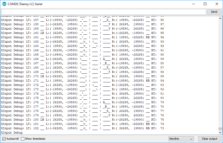
Debug Mode
I know this can get confusing and it can be difficult to keep track of what’s going on without being able to print over serial, so the library comes with a ‘debug mode’! Just set your USB-capable board to the non-XInput version and the library will print a nicely formatted output of all of the control states for you, instead of acting like an Xbox controller:
Rumble Motors and LED Patterns
The library also gives you access to the XInput data the Arduino receives. Namely, the state of the gamepad’s two rumble motors and the pattern playing on the LED ring.
There are two rumble motors: a ‘big’ one in the left grip and a ‘small’ one in the right grip. These are stored as 8-bit unsigned integers (0 – 255), where the normal state is ‘0’ for off. There are functions for getting these values separately, or combined into a single packed 16-bit value:
	uint8_t bigRumble = XInput.getRumbleLeft();
	uint8_t smallRumble = XInput.getRumbleRight();

	uint16_t bothRumble = XInput.getRumble();
The LED patterns work similarly. The pattern IDs can be retrieved by calling the getLEDPattern() function:
	XInputLEDPattern currentPattern = XInput.getLEDPattern();  // using enum
 	uint8_t patternID = (uint8_t) XInput.getLEDPattern(); // using unsigned int
You can find an enumeration of the available LED patterns in the library’s header file. This library does not handle the LED animations themselves. For that you can use the Xbox 360 Controller LEDs library. For more information on the LED animations, see this blog post.
If you want to deal with these values as they come in, check out the ReceiveCallback example.
Example: Rocket League Controller
Now that you know the basics of using the library, let’s build a simple example to put it into practice! In this case, a barebones controller for Rocket League.
Wiring
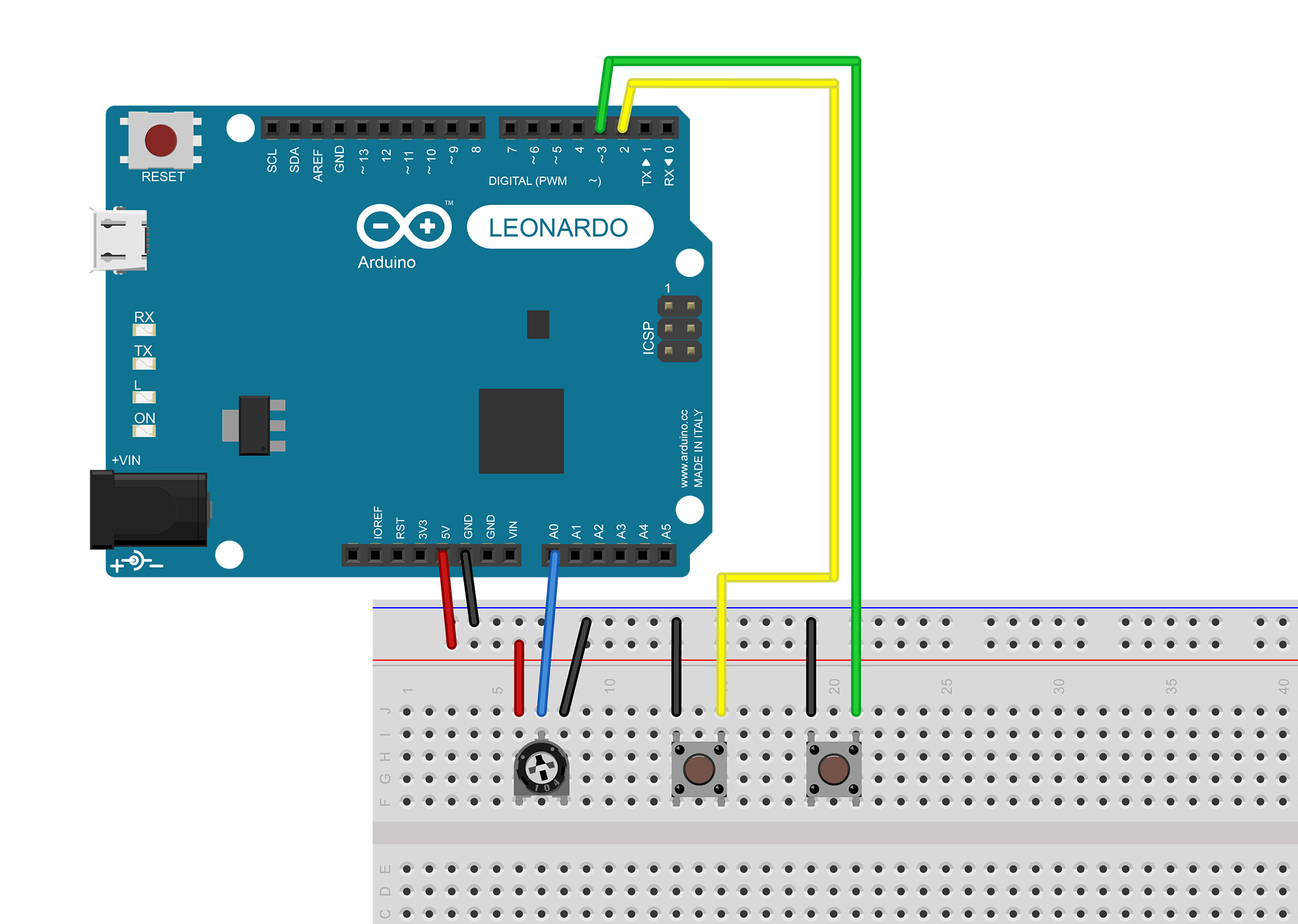
I’m going to be using some basic components that you should have on hand. You’ll need a breadboard, two tactile push-buttons switches, a 10K potentiometer or joystick, and an XInput-capable Arduino (I’m using an Arduino Leonardo). You’ll also need a few wires to connect everything together.
Both switches are going to be wired using the Arduino’s internal pull-ups. One pin of the button should connect to a digital IO pin and the other pin of the button should connect to ground. I’m using pins 2 and 3, but you can use whatever pins you like. The potentiometer should have pin 1 connect to 5V, pin 2 connect to an analog pin (I’m using A0), and pin 3 connect to ground. Here’s a Fritzing diagram of the completed circuit:
Programming
Now it’s time to connect these hardware inputs to the XInput outputs! There are a myriad of controls in Rocket League, but for now we’ll just focus on three:
- Turning – Left Joystick X Axis
- Moving Forward – Right Trigger
- Jumping – Button ‘A’
At the top of the sketch, we’ll start by including the library and then defining some constants for our pins:
#include <XInput.h>

// Input Pins
const uint8_t Pin_Joystick = A0;  // Turn left/right
const uint8_t Pin_ButtonA  = 2;   // Jump
const uint8_t Pin_TriggerR = 3;   // Accelerate

// Output Pins
const uint8_t Pin_LED = LED_BUILTIN;

// Analog Input Range
const int AnalogRead_Max = 1023;  // 10-bit ADC
Next up is the setup() function. Here we’ll initialize the pins we’re using, set the input range for the joystick (potentiometer), and ‘begin’ the library:
void setup() {
	// Set input pin modes
	pinMode(Pin_ButtonA, INPUT_PULLUP);
	pinMode(Pin_TriggerR, INPUT_PULLUP);

	// Set output pin mode
	pinMode(Pin_LED, OUTPUT);
	digitalWrite(Pin_LED, LOW);  // Turn 'off'

	// Setup library
	XInput.setRange(JOY_LEFT, 0, AnalogRead_Max);
	XInput.begin();
}
Then in the loop() function we’ll add the bits we want to run continuously. First we’ll read the pin states using the built-in digitalRead and analogRead functions and then assign those values to the XInput controls, which are automatically sent to the PC:
void loop() {
	// Read pin states
	boolean pressA = !digitalRead(Pin_ButtonA);
	boolean pressTrigger = !digitalRead(Pin_TriggerR);
	int joystickValue = analogRead(Pin_Joystick);

	// Set button and trigger states
	XInput.setButton(BUTTON_A, pressA);
	XInput.setButton(TRIGGER_RIGHT, pressTrigger);
	XInput.setJoystick(JOY_LEFT, joystickValue, AnalogRead_Max / 2);  // move x, leave y centered
	...
Note that the digital read functions have a not operator (‘!’) to invert the output because we’re using the pull-up resistors, so ‘LOW’ is ‘pressed’. You can also see that I’m treating the trigger like a digital output by using the setButton function instead of the typical setTrigger function that takes an analog value. The potentiometer value is written to the joystick ‘x’ axis, and the ‘y’ axis is centered based on the constant we set at the top of the code.
Lastly, we’ll check whether the Arduino has received any commands to turn on the rumble motors. If the motors are supposed to be rumbling, we’ll turn on the built-in LED. Otherwise, we’ll turn off the LED:
	...
	// Get rumble value
	uint16_t rumble = XInput.getRumble();

	// If controller is rumbling, turn on LED
	if (rumble > 0) {
		digitalWrite(Pin_LED, HIGH);
	}
	else {
		digitalWrite(Pin_LED, LOW);
	}
}
And that’s it! Just 50 lines of code and we’re up and running. Here’s the sketch in full:
/*
 *  Project     Rocket League XInput Demo
 *  @author     David Madison
 *  @link       partsnotincluded.com/tutorials/how-to-emulate-an-xbox-controller-with-arduino-xinput
 *  @license    MIT - Copyright (c) 2019 David Madison
 *
 * Permission is hereby granted, free of charge, to any person obtaining a copy
 * of this software and associated documentation files (the "Software"), to deal
 * in the Software without restriction, including without limitation the rights
 * to use, copy, modify, merge, publish, distribute, sublicense, and/or sell
 * copies of the Software, and to permit persons to whom the Software is
 * furnished to do so, subject to the following conditions:
 *
 * The above copyright notice and this permission notice shall be included in
 * all copies or substantial portions of the Software.
 *
 * THE SOFTWARE IS PROVIDED "AS IS", WITHOUT WARRANTY OF ANY KIND, EXPRESS OR
 * IMPLIED, INCLUDING BUT NOT LIMITED TO THE WARRANTIES OF MERCHANTABILITY,
 * FITNESS FOR A PARTICULAR PURPOSE AND NONINFRINGEMENT. IN NO EVENT SHALL THE
 * AUTHORS OR COPYRIGHT HOLDERS BE LIABLE FOR ANY CLAIM, DAMAGES OR OTHER
 * LIABILITY, WHETHER IN AN ACTION OF CONTRACT, TORT OR OTHERWISE, ARISING FROM,
 * OUT OF OR IN CONNECTION WITH THE SOFTWARE OR THE USE OR OTHER DEALINGS IN
 * THE SOFTWARE.
 *
 */

#include <XInput.h>

// Input Pins
const uint8_t Pin_Joystick = A0;  // Turn left/right
const uint8_t Pin_ButtonA  = 2;   // Jump
const uint8_t Pin_TriggerR = 3;   // Accelerate

// Output Pins
const uint8_t Pin_LED = LED_BUILTIN;

// Analog Input Range
const int AnalogRead_Max = 1023;  // 10-bit ADC

void setup() {
	// Set input pin modes
	pinMode(Pin_ButtonA, INPUT_PULLUP);
	pinMode(Pin_TriggerR, INPUT_PULLUP);

	// Set output pin mode
	pinMode(Pin_LED, OUTPUT);
	digitalWrite(Pin_LED, LOW);  // Turn 'off'

	// Setup library
	XInput.setRange(JOY_LEFT, 0, AnalogRead_Max);
	XInput.begin();
}

void loop() {
	// Read pin states
	boolean pressA = !digitalRead(Pin_ButtonA);
	boolean pressTrigger = !digitalRead(Pin_TriggerR);
	int joystickValue = analogRead(Pin_Joystick);

	// Set button and trigger states
	XInput.setButton(BUTTON_A, pressA);
	XInput.setButton(TRIGGER_RIGHT, pressTrigger);
	XInput.setJoystick(JOY_LEFT, joystickValue, AnalogRead_Max / 2);  // move x, leave y centered

	// Get rumble value
	uint16_t rumble = XInput.getRumble();

	// If controller is rumbling, turn on LED
	if (rumble > 0) {
		digitalWrite(Pin_LED, HIGH);
	}
	else {
		digitalWrite(Pin_LED, LOW);
	}
}
Soccar!
Time to take this baby for a spin! Upload the sketch, boot up the game, and head into Free Play (Training) to try it out!
Tweaking
It’s time to practice what you’ve learned! Try to make some changes to the Rocket League controller sketch. Here are some ideas to get you started:
- Change the ‘jump’ button (A) to ‘boost’ (B)
- Make the turning more responsive (narrow the range)
- Turn off the ball-cam (Y) whenever the controller rumbles
If you have the extra hardware, try replacing the potentiometer with a two-axis thumbstick or add a few extra buttons for the missing controls.
Further Reading
That should give you a good overview of how to use the ArduinoXInput library to emulate an Xbox controller. For further reading, check out some of the library’s built-in examples. You can find them either through the IDE by going to File -> Examples -> XInput, or in the library’s repository on GitHub.
This library opens up so many possibilities. Let me know what you create!