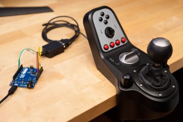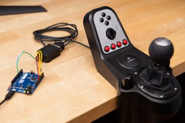
The new Logitech racing wheels come in two parts: the wheel “base” which contains the steering wheel proper, and an add-on peripheral with gas, brake, and clutch pedals. This pedal peripheral is quite well built with a metal frame, aluminum pedal faces, and user swappable springs. It even has mounting points for hanging the pedals upside-down or attaching them to a sim racing rig. Despite these perks, the pedals cannot function on their own – they must be plugged into the wheel base in order to work over USB. If you want to use these pedals with a different wheel setup, you need some sort of USB adapter.
I’m going to show you you can how to build your own DIY USB adapter for these Logitech pedals in under 15 minutes using only a handful of parts. This is an easy project and requires absolutely no soldering.
Supplies
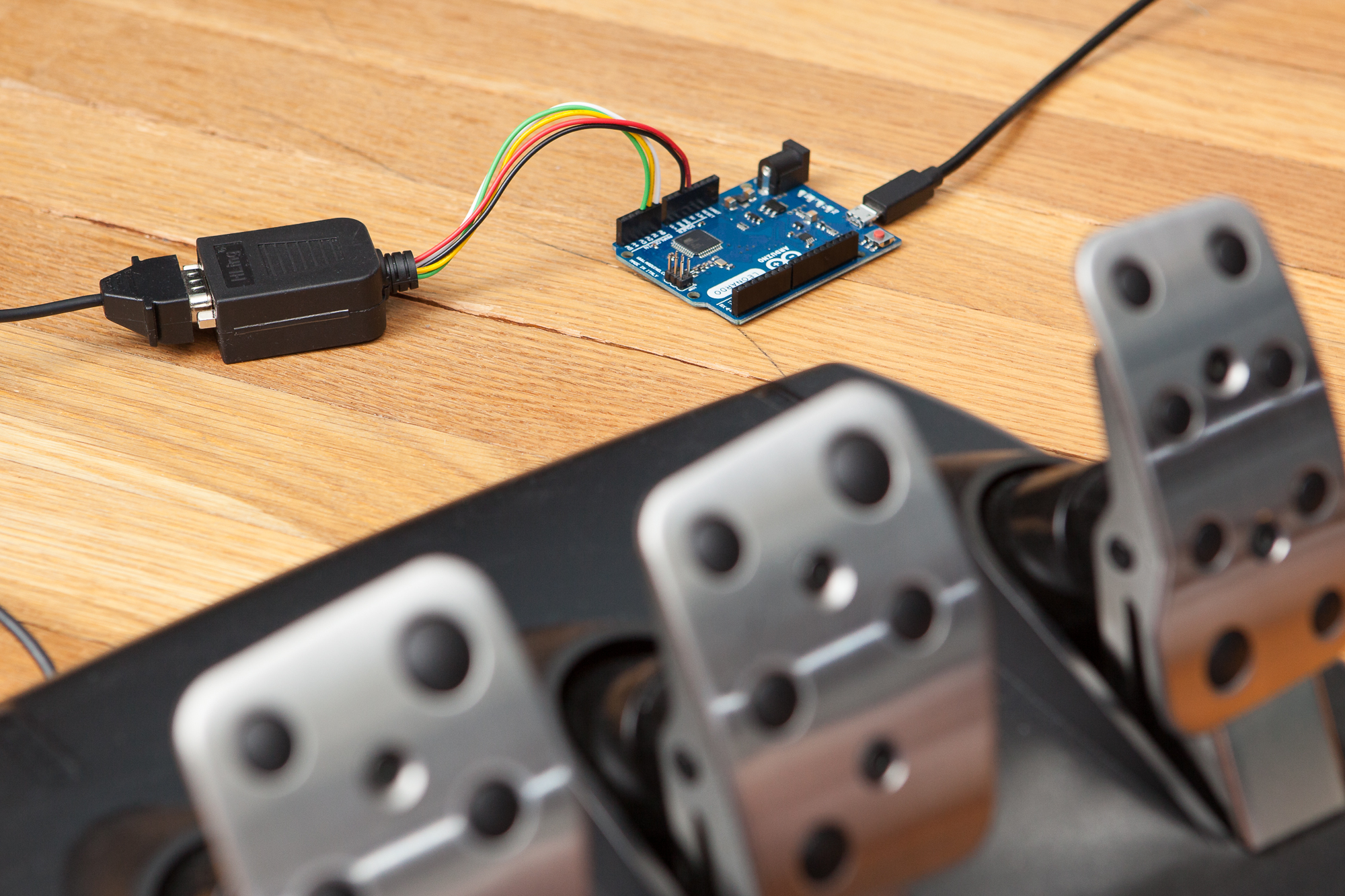
Here’s what you’re going to need to build this adapter:
- A DB9 female to screw terminal adapter
- A few pieces of solid-core wire, about 22 AWG
- An Arduino Leonardo (or a less expensive clone)
- A pair of needle-nose pliers
(These are affiliate links. As an Amazon Affiliate I earn from qualifying purchases.)
Please note that you cannot use an Arduino Uno, Nano, or Mega. They are not capable of running the included USB joystick firmware. You can use an Arduino Micro or SparkFun Pro Micro, although those will require you to solder to the headers.
It is important that you use solid-core wire and not stranded wire. This will ensure that you can get a good connection between the wire and the terminals on both the connector and the Arduino.
If you have access to a wire stripper and/or a pair of flush cut pliers I would recommend using those in place of the needle-nose pliers, although they’re not necessary.
Step #1: Prep the Wires
The first thing you’re going to do is cut the wires to length. We’re going to need 5 wires, each cut to about 7″ long. If you can, make each of these wires a different color. The colors I’m using are white, yellow, green, black, and red. Your wires don’t have to be color-coded, but it does make it much easier to assemble the adapter.
Using your pliers, strip off about 1/4″ from one end of each of the wires. Then grasp and bend the stripped portion until it’s at a right angle to the rest of the wire. Do not strip the other end of the wires just yet.
Step #2: Wiring
Remove the connector from its plastic casing. Using the included screwdriver, you’re going to loosen each terminal by turning counter-clockwise, insert a wire, then tighten the terminal by turning clockwise. The wires should be oriented away from the DB9 connector.
Here is the list of connections. Be sure to connect the wires one at a time in the same order as the table (top to bottom). This way, no wires will overlap the pins you’re trying to connect to. All five of the wires connect to a single pin and go towards the Arduino.
| DB9 Pin | Arduino Pin | Color | Function |
|---|---|---|---|
| 4 | A0 | White | Clutch |
| 3 | A1 | Yellow | Brake |
| 2 | A2 | Green | Throttle |
| 1 | GND | Black | Ground |
| 9 | 5V | Red | Power |
Double-check your connections, then slide the case’s rubber grommet onto the connected wires (with the flange facing towards the connector). Insert the connector back into its case, and then install the included screws and strain relief bracket. These will hold the wires securely so there will be less risk of the screw terminal connections coming loose. Close the connector’s case.
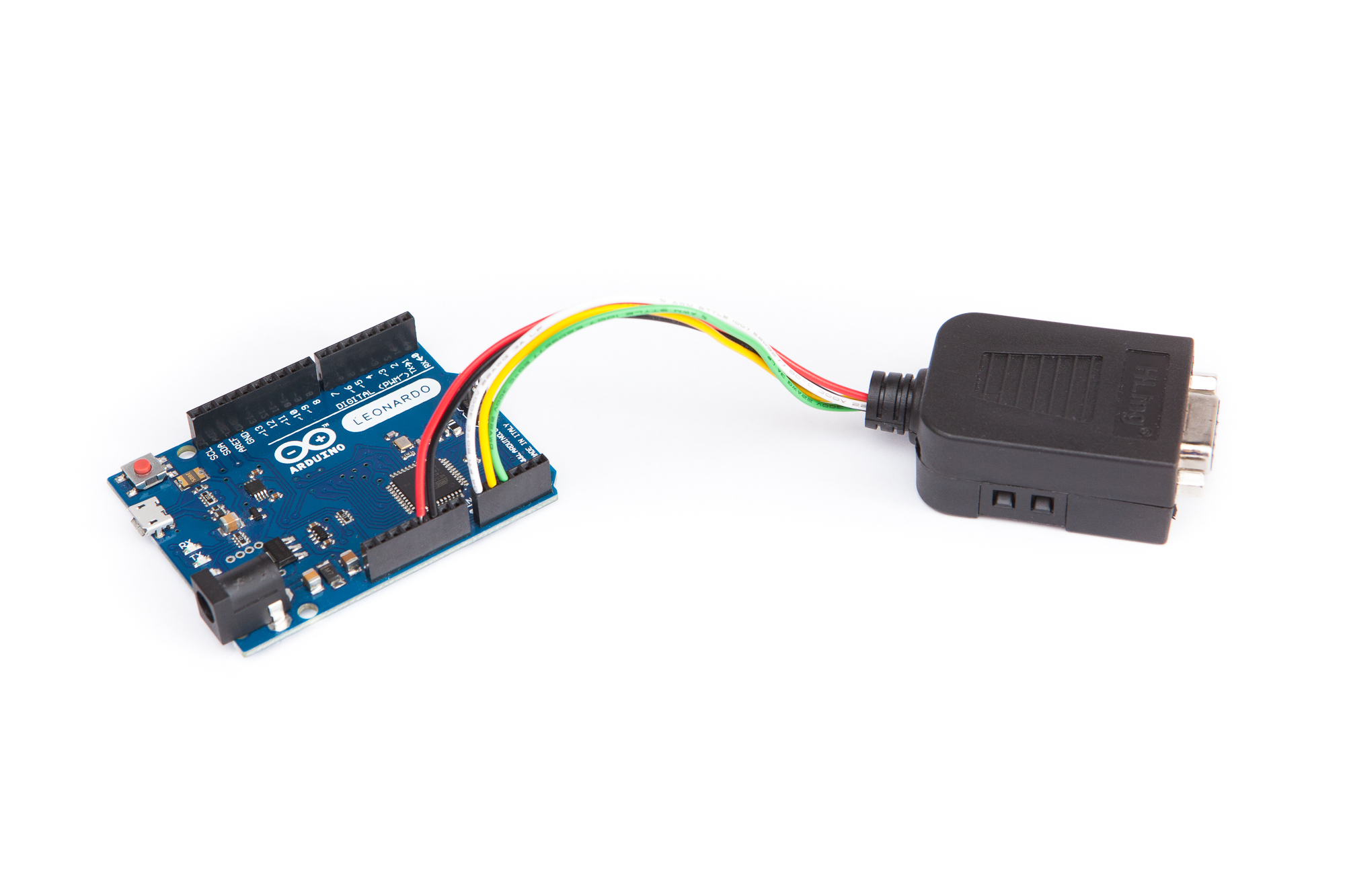
Now for the connections to the Arduino. Strip the other ends of the wires, again about a 1/4″. One at a time, insert the wires into Arduino following the table above. Unlike with the DB9 connector, the order in which you add the wires does not matter.
Once you have the adapter fully wired, double-check your connections before proceeding to the next step.
Step #3: Programming
Download and install the latest version of the Arduino IDE. You’ll also need two libraries:
Download both of these by clicking on the “Source Code .zip” links. In the IDE, we can install them by going to:
Sketch > Include Library > Add .ZIP Library
Add both libraries to the IDE. If you get stuck, take a look at the official libraries installation tutorial.
Once the libraries are installed, we’re going to load the Sim Racing Library example called PedalsJoystick. In the menu, go to:
File > Examples > Sim Racing Library > Pedals > PedalsJoystick
A new window should open with the example program. Back up in the menu, we need to set the board to the Leonardo:
Tools > Boards > Arduino Leonardo
While you’re there, look at the list of serial ports (Tools > Ports). Mentally note if there are any ports present, then close out of the menu. Plug in your Arduino and then open the ports menu once again, you should see a new port listed for your Leonardo. Select that port.
Now click the “Upload” button with the arrow icon in the upper left of the window. If all is well, the Arduino IDE will compile and upload the program to your Leonardo. Look for the “Done uploading” status in the window once it’s done.
Step 4: Play!
The adapter is complete! Plug in your pedals and take a look at your system’s joystick control panel. You should see the Leonardo as a controller, with three axes corresponding to the three pedal inputs. Load up your favorite racing game, assign the joystick axes to each pedal, and enjoy!
In the that case something doesn’t feel quite right, I highly recommend running your operating system’s joystick calibration routine. That will make the pedals work perfectly for you specific pedal set and your personal driving style. In Windows, you can find this calibration function in the joystick control panel (joy.cpl).
Looking for something more permanent? I designed a “shield” for the SparkFun Pro Micro that makes all of these connections out of the box. You can find that project here.
Have you built one of these adapters? Do you have advice for new builders, or suggestions for this article? Leave a comment below!