I recently put together a library for interfacing Arduino development boards with sim racing devices such as shifters, pedals, and handbrakes. The library makes it easy to retrieve the relevant data from those devices and send it to a racing simulator. The only catch is that the user has to carefully wire things up themselves, which is a little tedious and results in a somewhat messy final product.
To close that gap, I designed some custom sim racing “shields” which attach to the underside of an Arduino and make it quick and easy to connect to existing sim racing devices.
Board Design
I had two goals in mind while designing these shields. The first was to keep things simple, and the second was to keep things low cost.
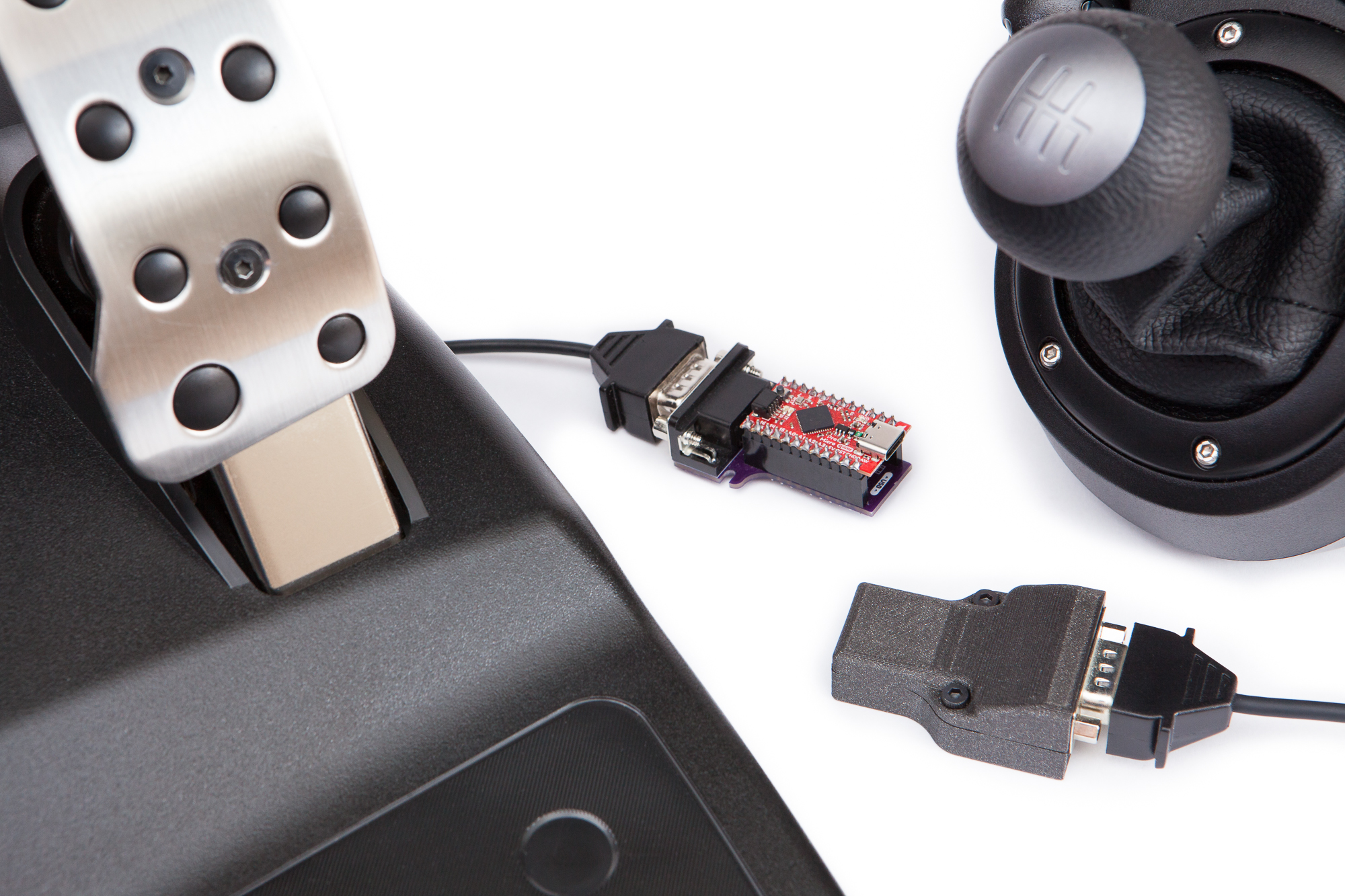
This meant that these boards are about as small and barebones as possible. They use an existing development board (a SparkFun Pro Micro) in place of a custom layout because it’s cheaper in low quantities and easier to assemble for a novice. The only components on the board are those that are absolutely necessary – the headers for the microcontroller, the connector for the peripheral, and resistors for the relevant pins. There’s no frills, but that also means there’s no complications.
On the underside of the board there are jumper pads for each connection, bridged where necessary and labeled with their functionality. This allows the user to customize or re-order the connections as needed for any project. I also included a Tag-Connect programming header for posterity.
Both shields use DB-9 (or more accurately, DE-9) connectors to attach to the peripherals. Although the format is the same the genders are different between the shifter and the pedals, preventing users from accidentally connecting things the wrong way.
The shields can be assembled with either 0.1″ female headers for prototyping or 0.1″ male headers for a permanent connection. Only assembled boards with male headers will be able to fit inside the 3D printed case.
In normal times the total cost of each of these shields, fully assembled, should be less than $10 USD. Less than $5 for the PCB, the resistors, and the peripheral connector, then a few dollars for a “clone” Pro Micro. Unfortunately the current worldwide chip shortage has created a scarcity of ATmega32U4 microcontrollers and put a damper on that target. As of this writing you can still purchase official SparkFun Pro Micro boards, although they are a rather pricey $20.
Other boards such as the SparkFun Pro Micro RP2040 that match the footprint and pinout of the original Pro Micro are theoretically compatible but have not been tested.
Shifter Shield
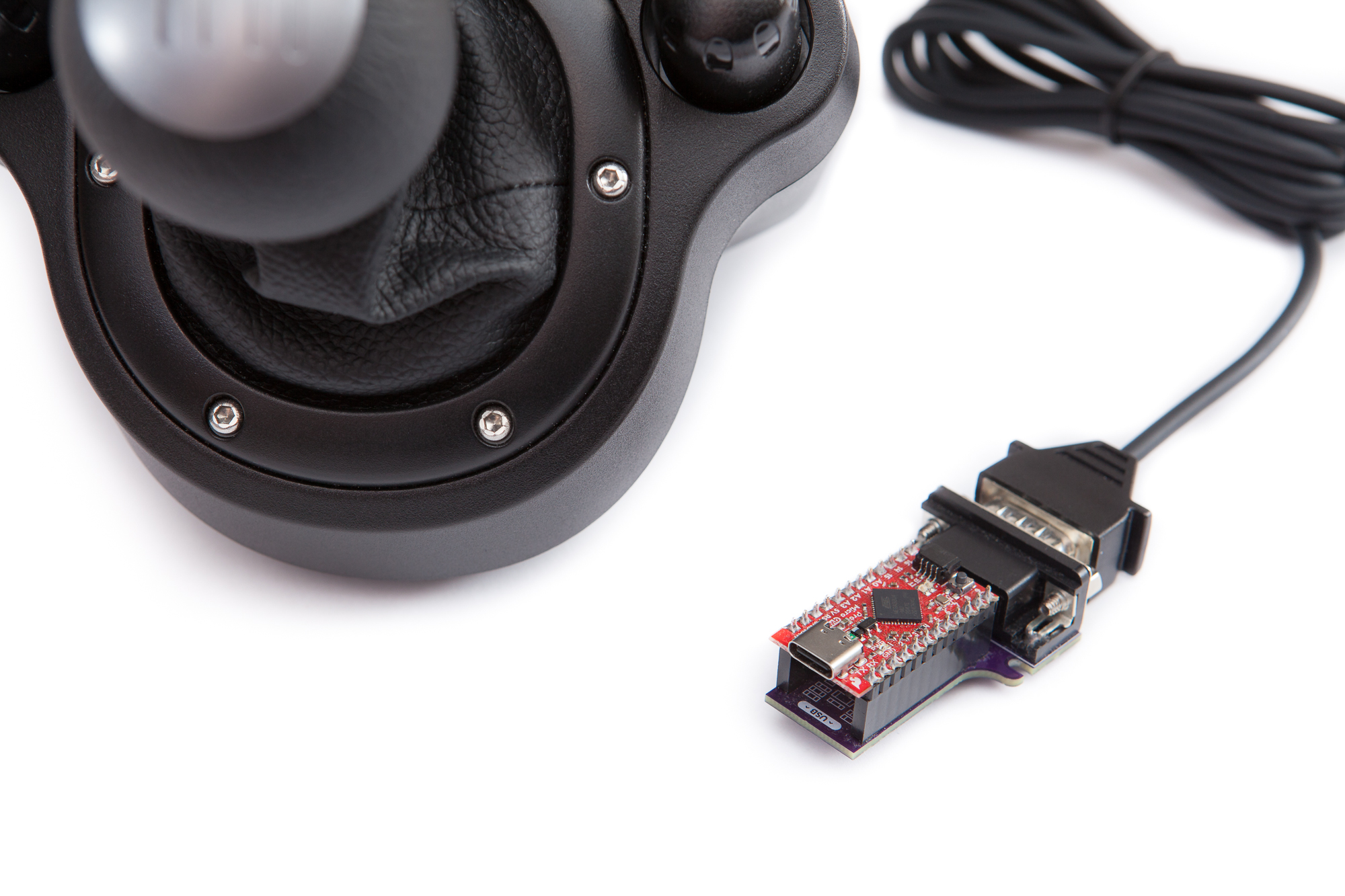
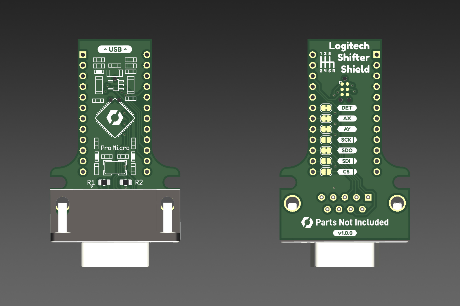
The shifter shield is designed to interface with Logitech shifters using a single DB-9 male connector. It’s compatible with all of Logitech’s available shifters at the time I’m writing this, including the “Driving Force” shifter (G923 / G920 / G29) and the shifters included with the G27 and G25 wheels. Using the Sim Racing Arduino library it’s possible to get both the current gear the shifter is in as well as its absolute position and the state of any buttons.
In addition to retrieving gear data, the shield is able to detect whether the shifter is connected or not and control the built-in LED (if present). You can use the SimRacing::CreateShieldObject() template function in the library for easy setup when declaring a shifter class instance:
LogitechShifterG29 shifter = SimRacing::CreateShieldObject<SimRacing::LogitechShifterG29, 2>();
LogitechShifterG27 shifter = SimRacing::CreateShieldObject<SimRacing::LogitechShifterG27, 2>();
LogitechShifterG25 shifter = SimRacing::CreateShieldObject<SimRacing::LogitechShifterG25, 2>();
The shield is also configured to support a connection between the Pro Micro’s hardware SPI interface and the EEPROM chip onboard these shifters. Although the library is not currently configured to talk to these EEPROMs in software, the shield’s hardware makes it easy if you want to experiment.
Pedal Shield

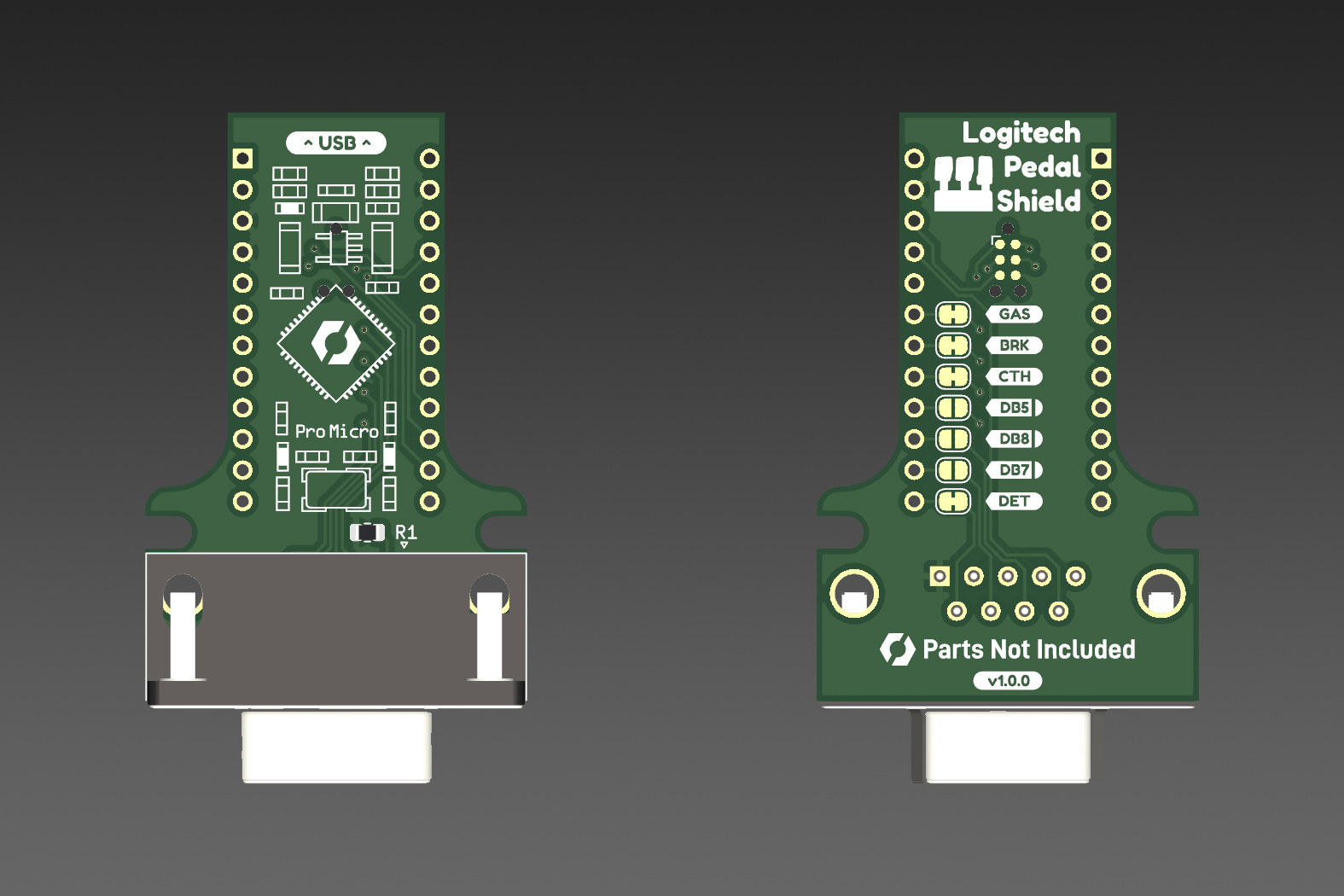
The pedal shield is designed to interface with the Logitech three pedal attachment, included with the Logitech G923 “TRUEFORCE”, G29/G920 “Driving Force”, and G27/G25 wheels, via a single DB-9 female connector. Using the Sim Racing Arduino library it’s possible to get the calibrated and raw positions of all three pedals.
As with the shifter, the pedal shield is able to detect whether the pedals are connected or not. You can use the SimRacing::CreateShieldObject() template function in the library for easy setup when declaring a pedal class instance:
LogitechPedals pedals = SimRacing::CreateShieldObject<SimRacing::LogitechPedals, 2>();
Note that this shield is not compatible with the two-pedal peripheral, included with some older Logitech wheels. While these pedals share the same connector the wiring pinout is incompatible.
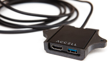
Enclosure
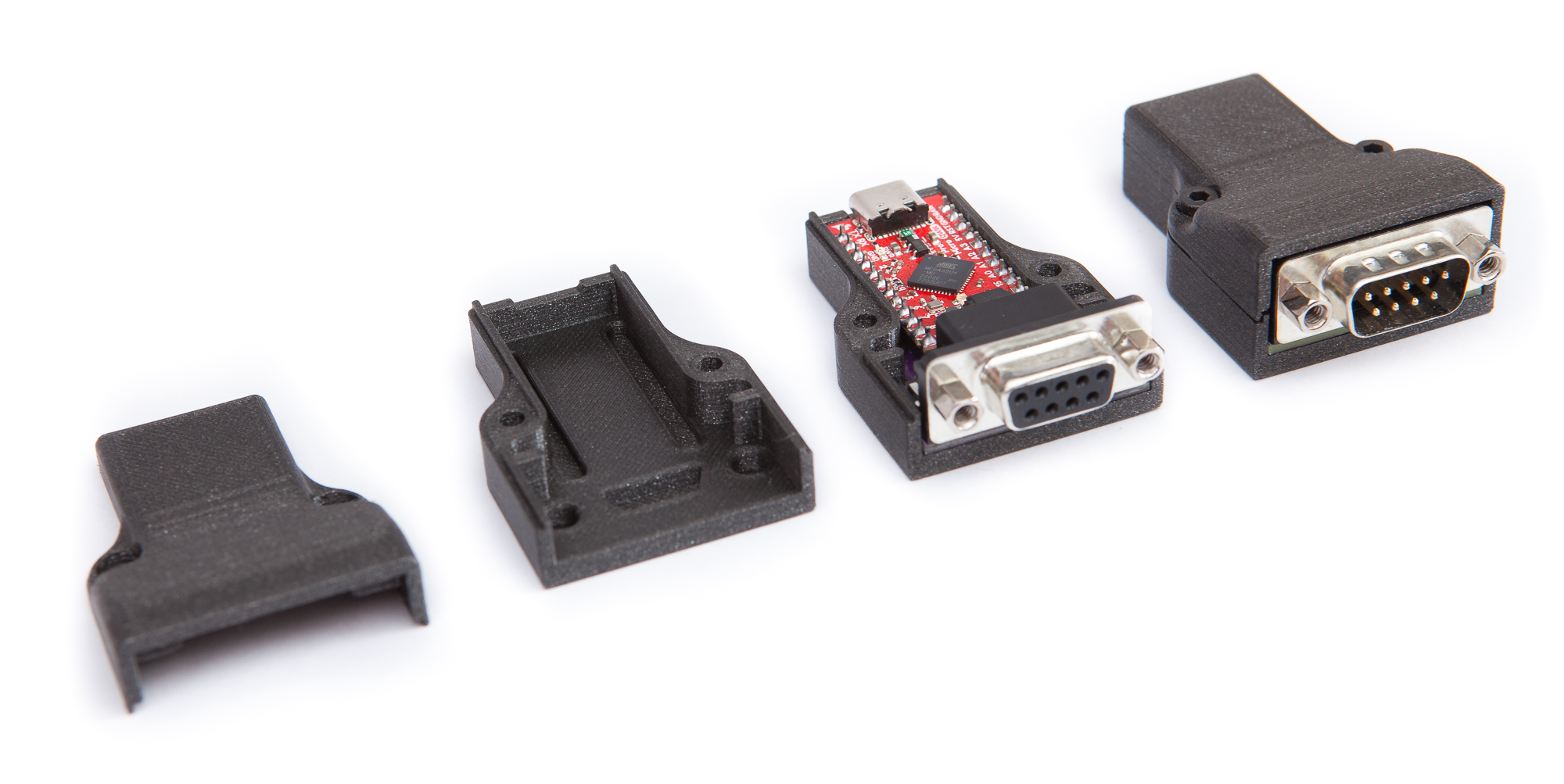
Both shields can either be used standalone or protected with the provided 3D printable enclosure.
The enclosure is a two-part design, with the midline split around the same level as the microcontroller. Cutouts on either side of the shield, just behind the DB-9 connector, prevent the shield from sliding back and forth. The two case halves are aligned with a thin perimeter and held together with a pair of M3-10 bolts with matching nuts. When the case is assembled, the design holds the microcontroller and shield securely without any play.
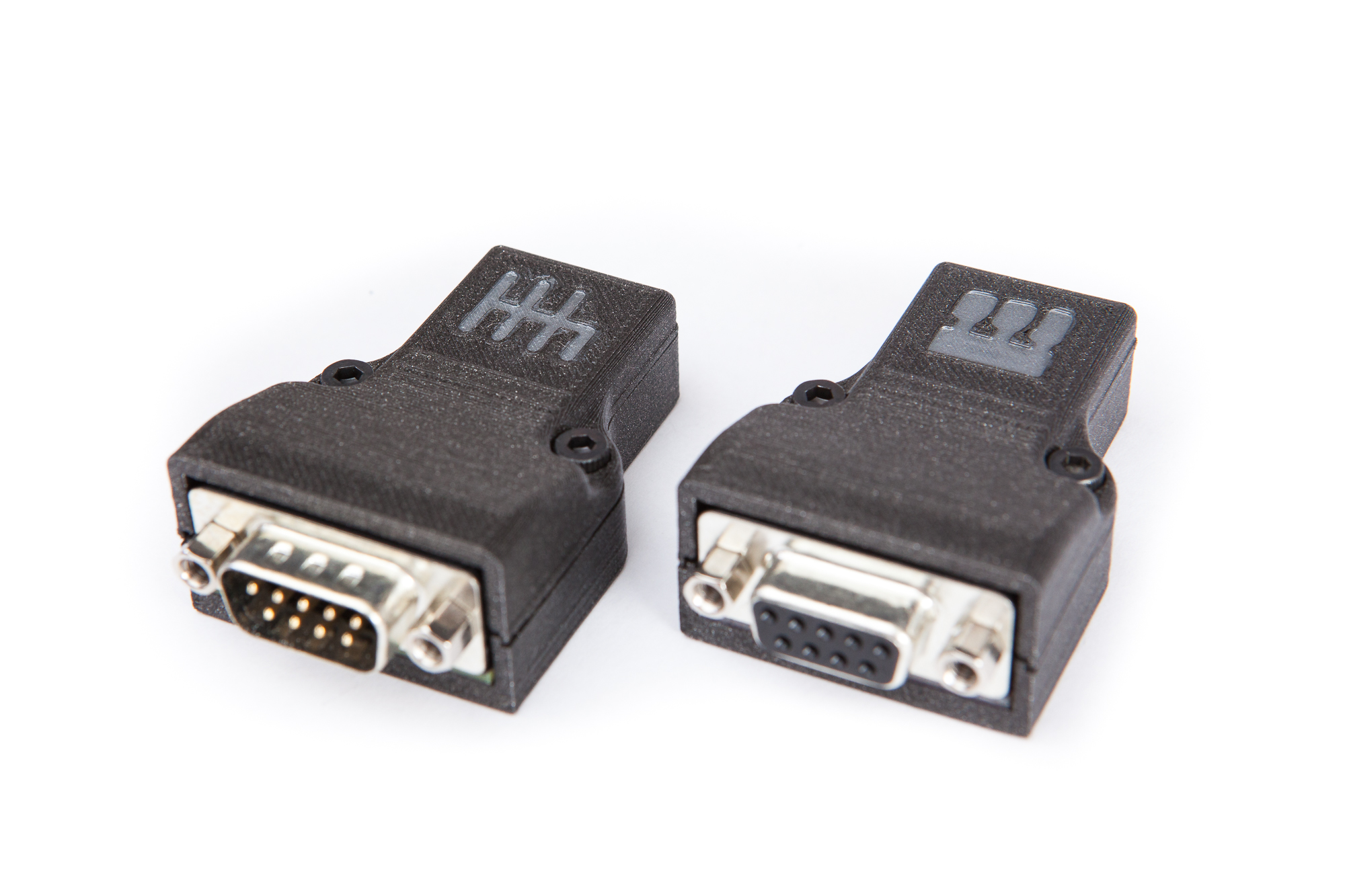
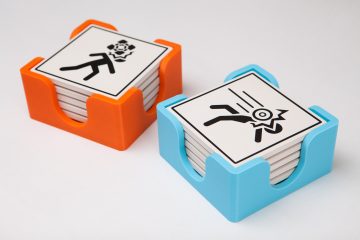
My own cases were printed out of glitter black PLA on my Prusa i3 MK3S+ and add a high level of polish to the project. Since I made both a shifter and a pedals adapter, I printed some custom case tops with debossed shifter/pedal symbols to tell them apart at a glance. I thinned out some gun metal airbrush paint from an old project and brushed it on to provide a little contrast, then sealed the paint in with some flat clear coat.
Firmware
As mentioned above, these shields are designed to be used with the Sim Racing Arduino library. Sketches can be compiled and uploaded using the SparkFun Pro Micro board definition in the Arduino IDE, with the same process you would use to upload to any other board.
The shields repository includes firmware for both the shifter shield and pedal shield to function as USB HID adapters, compatible with any racing game or simulator. Compiled .hex files are included in the latest release.
Board Definitions
This project goes one step further. The repo includes custom board definitions for the SparkFun Pro Micro that provide:
- A custom USB vendor identifier (VID)
- A custom USB product identifier (PID)
- A custom USB product description string
- A way to optionally disable the USB CDC serial interface
With these changes, it’s easy to program the Pro Micro and shield combination as a standalone USB converter that presents itself to your computer as a “Sim Racing Shifter” or “Sim Racing Pedals” instead of as a “SparkFun Pro Micro”.
The ability to disable the USB serial interface also improves compatibility with some systems and games, and prevents accidental reprogramming. This way you can leave the microcontroller and shield connected at all times without having to worry about accidentally changing the firmware.
These options are easy to select from within the Arduino IDE (in the Tools -> Boards menu). If you don’t want to bother with setting up the board environment, I am also planning to provide compiled binary files for the standard USB conversion firmware.
Make Your Own
Interested in one of these for yourself? Don’t fret, these shields are open source (GPLv3)! Everything is hosted on GitHub, click this link to go to the repository.
Have you assembled your own shield? Leave a comment below!
This article includes Amazon affiliate links which help fund the content on this site. As an Amazon Associate I earn from qualifying purchases.