When the sixth generation of video games consoles were released in the mid 2000s, console manufacturers began the process of transitioning from wired to wireless controllers. Both the PlayStation 3 and the Xbox 360 came with wireless controllers but offered wired options for gamers still reluctant to move on from the bulky tethers of yore. Similarly, many 3rd party controller manufacturers were hesitant to switch to the new wireless systems and only offered their controllers with bulky, permanently attached cables.
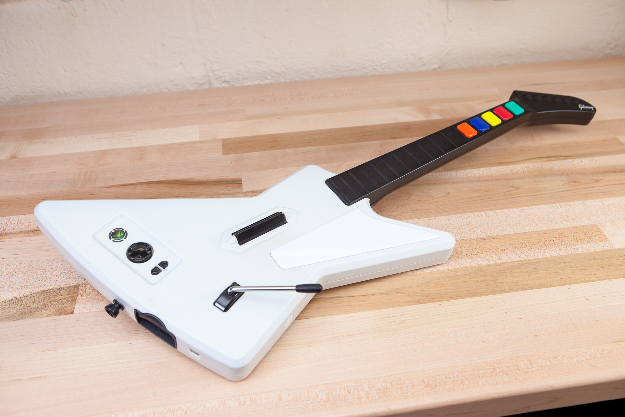
One such controller is the Guitar Hero X-Plorer, an Xbox 360 rhythm controller made by RedOctane. Modeled after a Gibson Explorer, the X-Plorer was released with Guitar Hero 2 and is still a popular choice today for Guitar Hero and Clone Hero players. It comes with a permanently attached 10 ft. USB cable that is great for playing from the couch, but is long and unwieldy when sitting at a desk.
To solve this problem, I’m going to remove the cumbersome USB cable and replace it with a sleek and modern USB-C jack.
Video
Disassembly
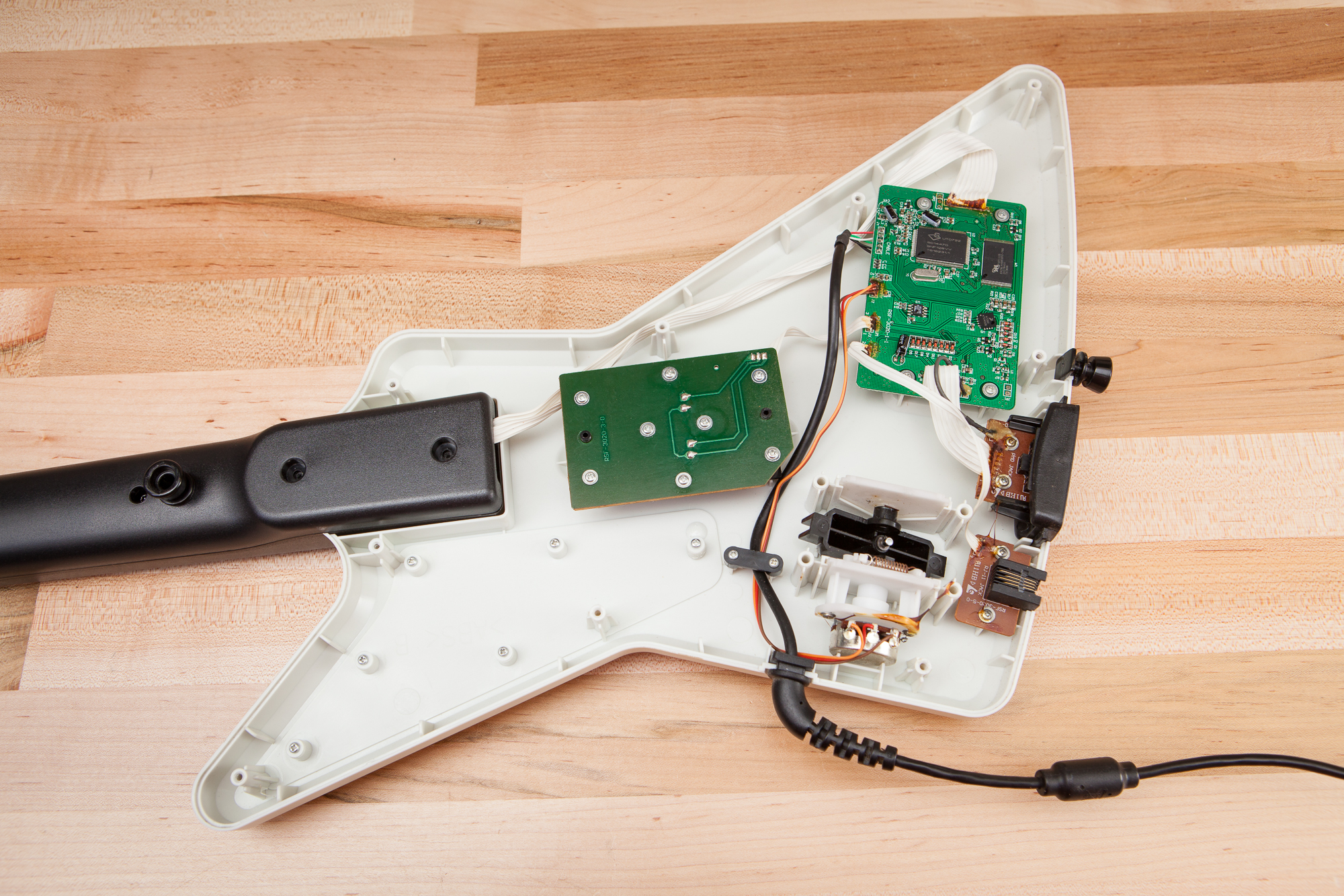
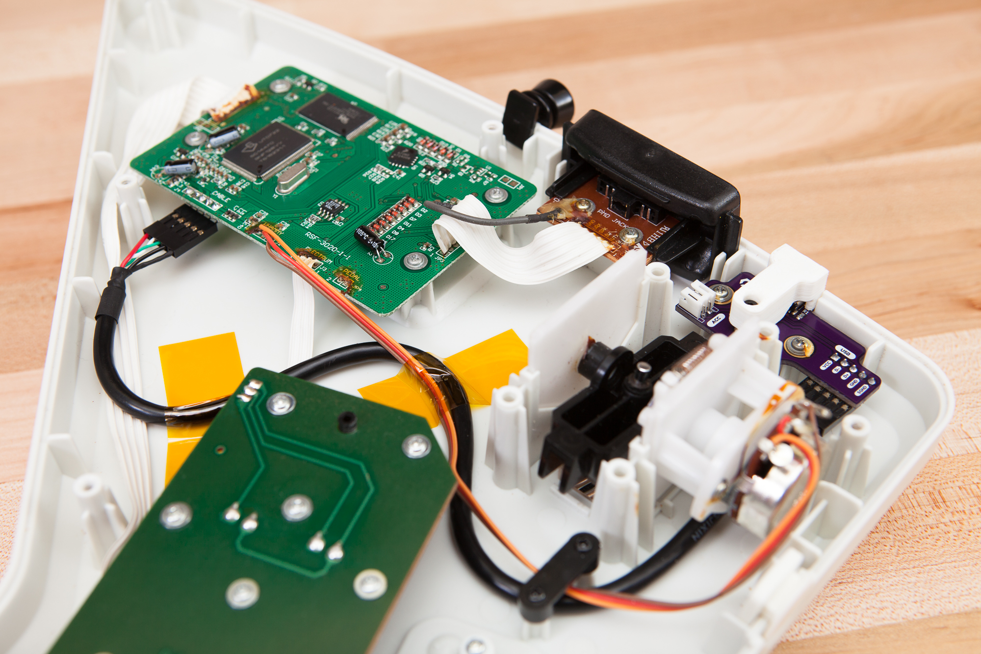
The first step in this process is to take the guitar apart and see what we have to work with. The main body is held together with 11 M3 plastic-cutting screws, accessible from the back. These all have Torx T10 heads and thankfully unlike the official Xbox 360 controller are not security screws. Nine of these around the perimeter are 10 mm long, while the two inline with the neck are 14 mm. These come out easily with a few turns of a screwdriver, and then the back of the guitar lifts off with no resistance. No cable connections exist between the two shell halves, and thankfully there’s no adhesive or plastic clips keeping everything together. Simpler times…
USB Wiring
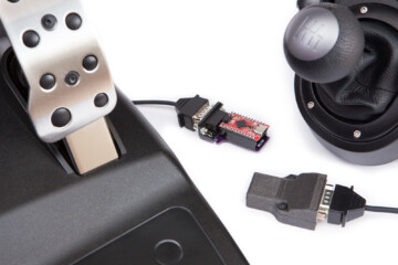
The guitar uses a purpose-built, proprietary USB cable. It includes a breakaway connector (proprietary Xbox 360 to USB-A) so the guitar won’t pull the console off of its shelf, a ferrite choke, and a right angle strain relief boot molded directly into the cable. This molded boot has a rectangular notch that mates with the body of the guitar so that cable strain is transferred to the housing and not the electrical connections within.
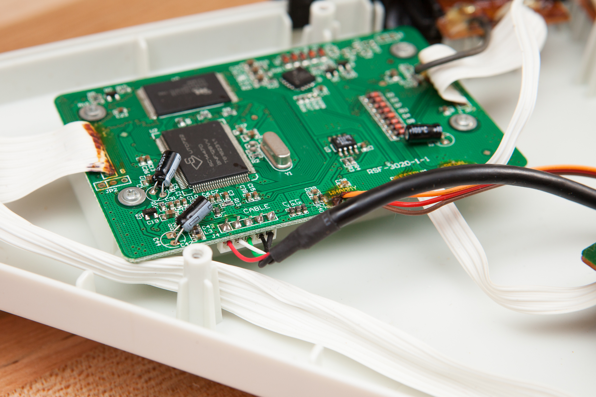
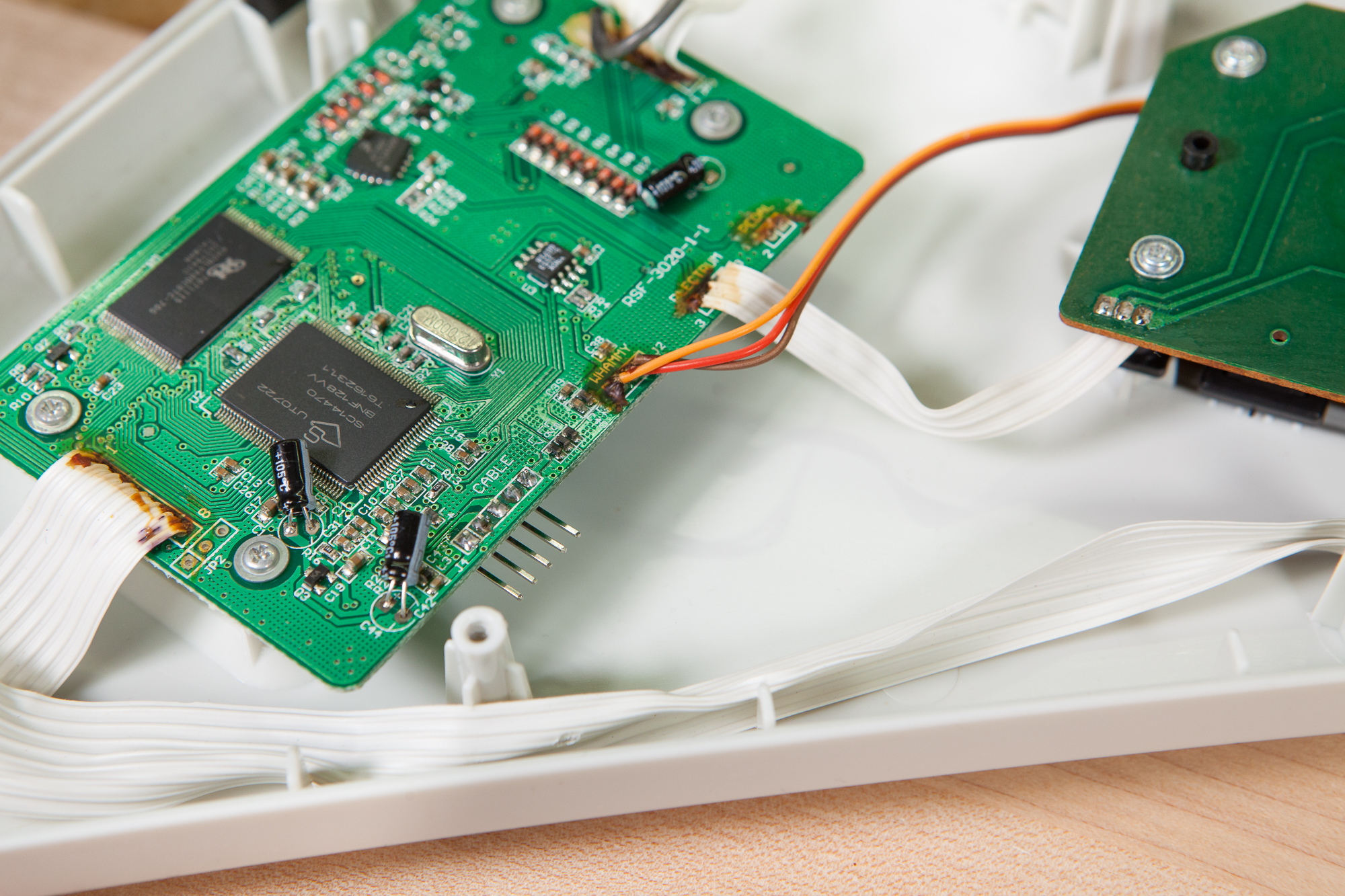
Inside the guitar, the cable is split into a 5 pin connector with crimped right angle pins soldered to the main circuit board. The wire colors and header pinout follow the standard USB 2.0 convention as used on computer motherboards:
| Function | Wire Color | Pin Number |
|---|---|---|
| VCC | Red | 1 |
| D- | White | 2 |
| D+ | Green | 3 |
| GND | Black | 4 |
| SGND | Black | 5 |
Although at first glance it looks like there is a female header on the board, these pins are in fact soldered directly to the main board with the plastic housing just holding them together (a “board-in” connector). This was a little frustrating to discover because it means this mod won’t just be a plug and play swap, but that’s nothing we can’t work around.
After triple-checking the pin assignments and their order I used a pair of flush-cut pliers to cut the USB cable as close as I could to the crimped pins. I then removed the plastic connector holding the pins together and desoldered each pin in turn. Because I was filming for YouTube at the time I wasn’t paying as close of attention as I should have and accidentally lifted half of the pad of the D- pin. Thankfully the half of the pad connected to the trace is intact so the header is still functional.
The pads on the board are 0.1″ (2.54 mm) apart, and the header’s proximity to the edge of the PCB means it’s not a good candidate for a full-size connector housing that incorporates positive locking (such as a Molex SL 70553). Instead, I soldered a plain 0.1″ right angle male header to the contacts and then crimped on a mating connector to the original USB cable. This restores the status quo but with one big upgrade: it allows the cable to be swapped out! Whether this mod works or not it will still be possible to revert to the original setup with the attached cable.
Vestigial Ports
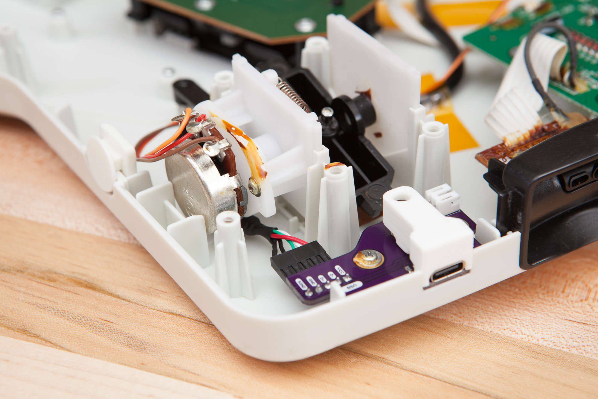
The target for this mod is the RJ11 “phone jack” port on the edge of the guitar. This was originally made for an external “effects pedal” concept but was never implemented. It’s the perfect target for replacement as the port is unused, has a pre-made cutout in the guitar body, and already includes molded mounting points. Reusing the existing cutouts and mounting points will make the mod significantly stronger and cleaner. (And easily repeatable on other guitars, to boot.)
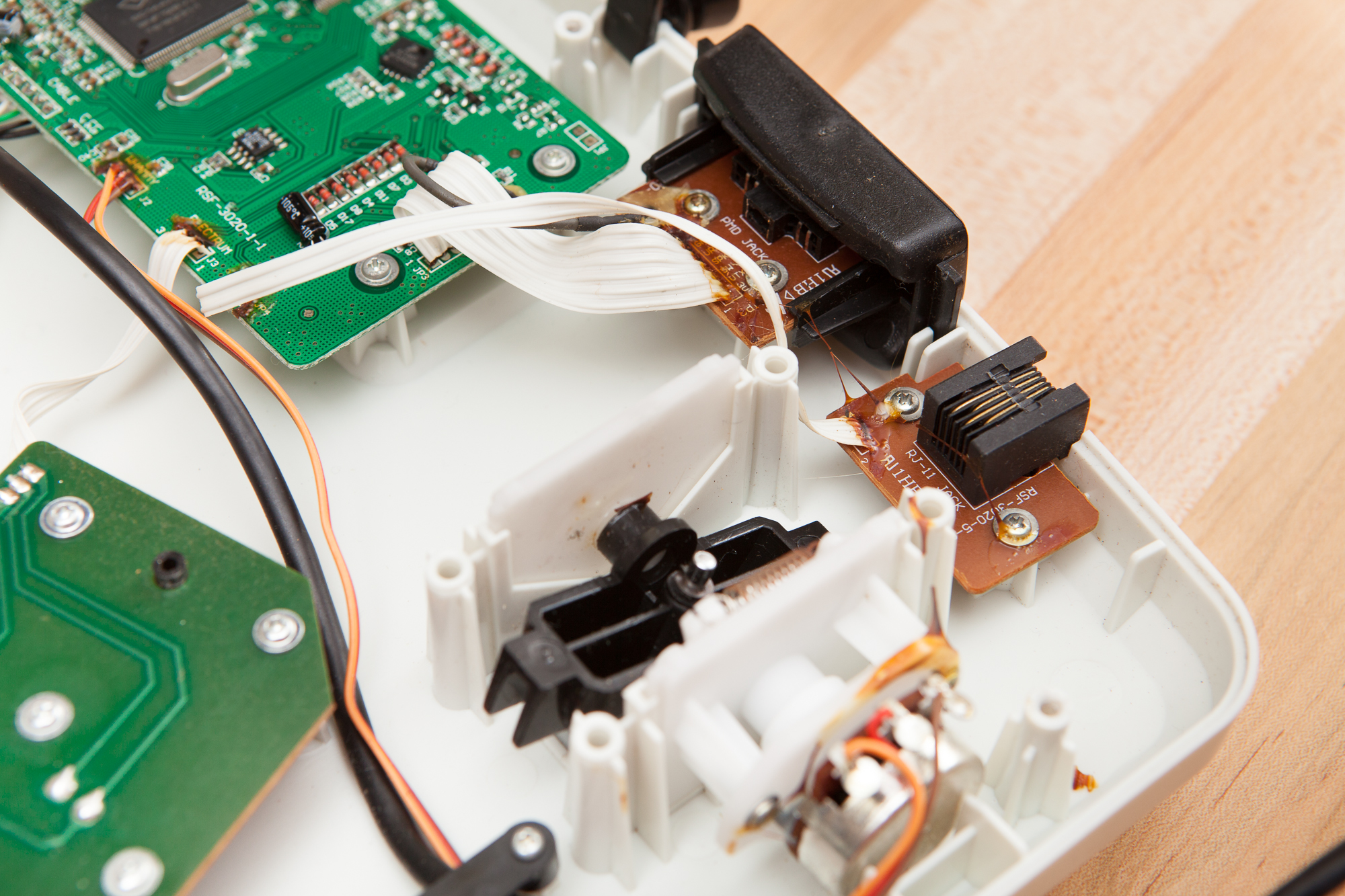
The daughterboard with the RJ11 port is a single-sided PCB approximately 34 by 22 mm in size, held in place with two M2.4-8 plastic-cutting screws with flange-heads 6 mm in diameter. The cutout for the port in the side of the guitar is sized perfectly around the RJ11 port (~13.5 x 12 mm W*H), which is just wide enough for the USB-C port with heaps of headroom above it.
A two-wire ribbon cable connects this daughterboard to the main PCB. I used a pair of side cutters to cut the connection at its base on the main board, then unscrewed and removed the PCB. The ribbon cable has no polarity indications, but if I ever want to reinstall the port there are silkscreen pin identifiers on both the main PCB and the daughterboard. I didn’t bother with adding a removable connector for this since it’s unused anyways, but this is the one change that is not plug and play for reversing the mod (the wires would need to be stripped and re-soldered). Although as the port is unused it would be just as well to screw it back in place without re-soldering the connection.
As an aside: it seems that much hay has been made online about whether this is an RJ-11 port or an RJ-14 port. Both ports use the same mechanical connector, but RJ-11 ports are 2-conductor and RJ-14 ports are 4-conductor. This port has 4 conductors but it’s on a PCB with only 2 output pins, which means it’s an RJ-14 port being used where only an RJ-11 port is needed (presumably for cost reasons). This is all to say that I’m going to call it RJ-11 because that’s what’s written on the PCB and RJ-11 is more well known, even if the specific connector used on this board is actually an RJ-14.
PCB Design
The next step is to design my own circuit board to take the place of the RJ11 daughterboard. This is going to have a USB-C port, a USB header for connecting to the guitar’s main board, and the associated circuity to make everything function.
Physical Layout
I started by measuring the daughterboard and created a model of the outlines and mounting holes in Fusion 360. After double-checking my work with a paper copy it was time to make some adjustments.
First, the USB port. The RJ11 port is chunky and its mounting pins sit back away from its outer edge. The USB-C port is much smaller and is close to flush with the outside edge of the PCB. To accommodate this I created a small offshoot from the board for the port to sit on – just wide enough to fit in the body opening previously occupied by the RJ11 port. This means the PCB edge is going to be visible from outside the guitar, but that’s preferable to having to recess the port and use a specific-width USB cable.
I also extended the right side of the PCB significantly to accommodate the chunky 5-pin 0.1″ pitch connector for the internal USB cable. The whammy bar makes packaging much more difficult than it initially looks. The header is placed as close to the whammy’s mounting points as possible so that the cable can run underneath the gap between the whammy’s support wall and the potentiometer body.
Electrical Schematic
The schematic for this is as barebones as possible. All of the work in handling electrostatic discharge (ESD) should already be taken care of on the main PCB, so this little board just needs to convert the downstream USB-A port into a USB-C port.
In addition to the USB-C connector (with only the USB 2.0 pinout for simplicity), I also needed to add two “cable connection” (CC) and cable type resistors to indicate that this was an “upstream facing port” (UFP). These are small 5.1k resistors from the CC lines to ground (two of them because the Type-C cable is reversible). The five necessary pins from the USB-C connector then run directly to the pin header for connecting to the internal USB cable.
For good measure I added an additional 2-pin JST connector to supply power and ground for any future guitar mods. To play it a little safer I also added a 500 mA polyfuse so that I don’t accidentally overload the host port with my shenanigans.
PCB Layout
Since this is such a simple design, routing the PCB was straightforward. I tried to stick to best practices for the USB data traces but since the guitar is only a “full speed” (12 Mbps) USB device I wasn’t too concerned. I also got to play around with KiCad’s differential trace skew matching feature for the first time which was rather fun.
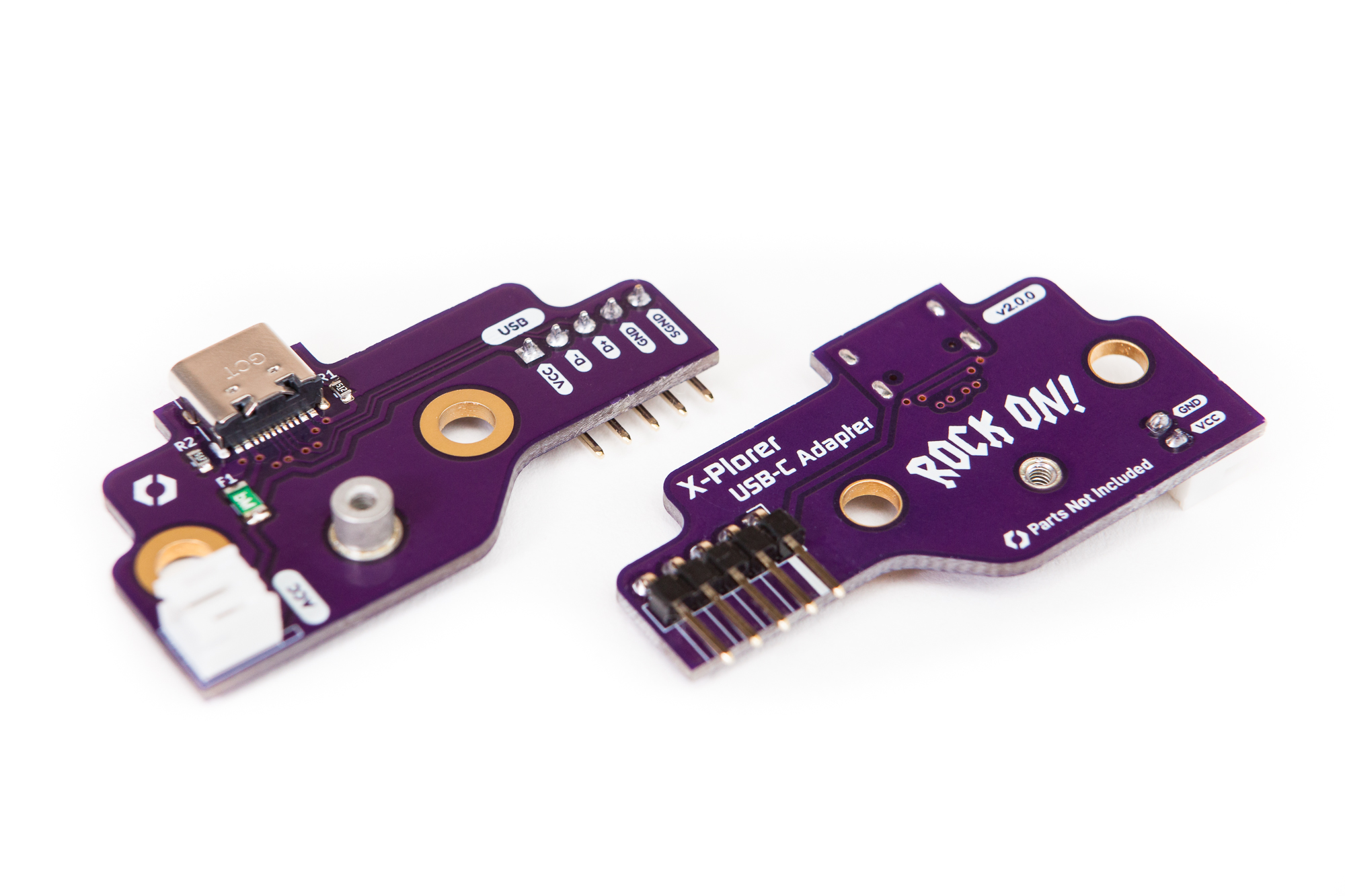
To finish it off I created a few snazzy graphics to give the board some polish, including some “ROCK ON!” text inspired by the “Rock Meter” from Guitar Hero 2. Plus the typical site logo, pin labels, and pedigree information.
Eagle-eyed readers may notice that this is version “2.0.0”. Originally I mis-measured the guitar’s USB header as 2.0 mm pitch and designed a PCB with a JST PH connector. I discovered the error as soon as the JST parts arrived, but by then it was too late to change the design. That board had the connector at a right angle to the whammy bar and when installed put too much stress on the connection for comfort. That issue also gave me a good excuse to redesign the board, using the correct pin spacing and an off-the-shelf cable.
(Pop quiz: if a connector has 5 pins and the total width is ~10 mm, what is the pitch? If you, like me, answered “2 mm” without thinking it through then you may also need to redesign your circuit board.)
Assembly
After waiting a few weeks for the board to be manufactured and the components to arrive, it was finally time for assembly.
I splurged on a nice stencil from OSH Stencils which made soldering a snap. After spreading the paste and placing the components with some serious tweezer skills, I reflowed the board using my trusty toaster oven and Reflow Master controller. I had some difficulty with the USB-C pads bridging, but nothing that a little flux couldn’t fix.
Once I had hand soldered the USB header and JST connector it was time for installation. In its original configuration with the RJ11 board, the bottom of the port cutout in the guitar body is even with the top face of the circuit board. With the USB-C mod this opening needs to be expanded slightly so it’s level with the bottom of the circuit board (a difference of 1.6 mm). This allows the PCB to extend into the opening so that the USB-C port can lie flush with the outside of the guitar body.
In the existing cutout there is a slight notch in the center where the release latch for an RJ11 connector can sit. I made a pencil mark on this notch and then used a flat needle file to even the cutout to that level.
The board sits snugly onto its mounting points and is screwed down using the original screws. For the internal USB cable I ordered a premade 12″ shielded cable from StarTech. This is maybe an inch longer than necessary, but it’s much easier and higher quality than building or modifying a cable myself. After connecting the cable between the adapter and the mainboard, I plugged in a USB-C cable and gave the guitar a test. We have liftoff!
Filling Gaps
To finish the mod I need to close up the newly opened holes in the shell.
The first of these is the leftover hole from the molded USB cable that exits from the bottom of the guitar. The molded strain relief boot has notches it in that mate with the notched square hole in the guitar. This prevents the USB cable from spinning and lets the boot transfer handling forces to the guitar body. Using the boot as a reference, I designed a small plug in Fusion 360 and 3D printed it out of white ABS. After a little sanding it fits flush with the outside of the guitar, almost like it was meant to be there in the first place.
The second one of these gaps is a little trickier. This is the void left from the absence of the RJ-11 connector. There’s a ~13 by 8 mm hole above the USB-C connector which needs to be filled to make the perimeter of the guitar look seamless.
Thankfully I thought about this while developing the PCB. In the middle of the board, just behind the two mounting points, I added a threaded standoff which is at the same height as the USB port. The plug I designed floats above the USB port and can be bolted into the PCB to secure it. This prevents it from moving forwards and back, while the edges of the hole in the guitar body prevent it from moving side to side. When the back shell of the guitar is screwed down, there is also a plastic standoff that pushes into the top of the plug to provide some extra pressure and keep things in place.
The standoff isn’t strictly necessary. It would be just as well to add a captive nut or threaded insert to the standoff itself, but the standoff makes assembly a tad bit easier since it can be added or changed without removing the PCB from the guitar body.
Complete
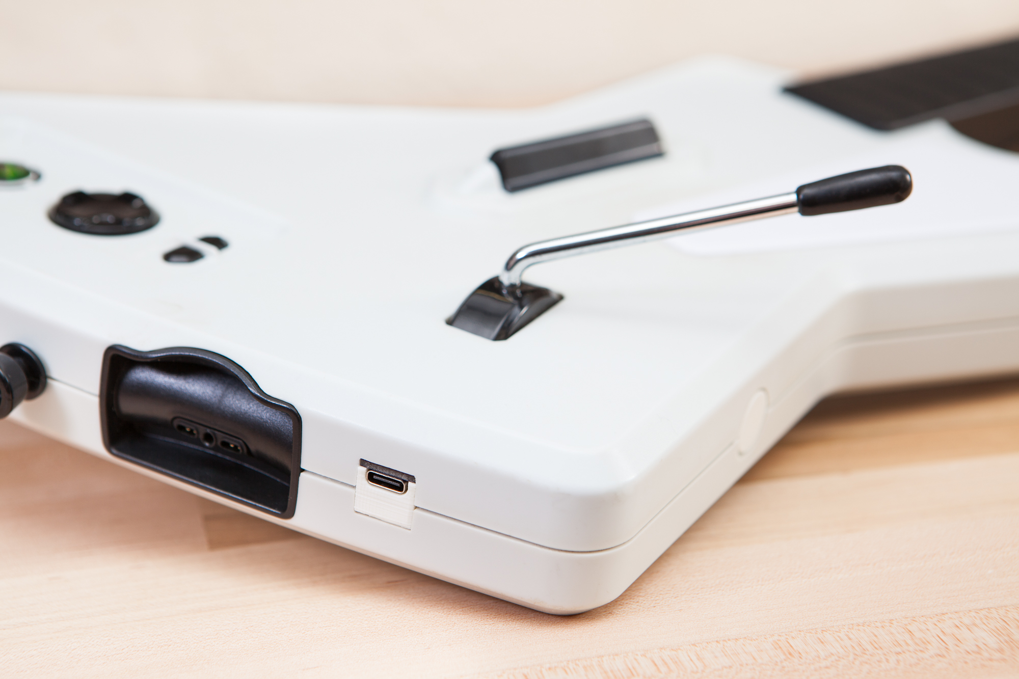
And with the back re-attached, the mod is complete! I plugged a fancy new USB-C cable into the side, connected it to Clone Hero, and full combo’d Through the Fire and Flames on Expert Medium. Because this is just a connector mod and doesn’t replace this rest of the electronics, the guitar maintains all of its original functionality including headset audio and console compatibility.
The USB-C port is a significant upgrade. No more messy cable hanging off the guitar at all times. The ability to swap to shorter or longer cables depending on whether you’re playing at your desk or on your couch. Compatibility with all modern USB cables. An easily accessible power port for future modifications. And no more ugly RJ11 port on the side of the guitar. (Okay, admittedly that one’s pretty minor.)
The one notable disadvantage of this mod is the lack of a breakaway connector. If you yank on the USB cable in the wrong way it may bend or break the USB cable or the connector inside the guitar. If you’re really unlucky it’ll break the mounting points on the inside, at which point you would need to get a new shell or go back to the original USB cable.
Future Changes
I’m pretty happy with how this turned out. But as with all projects, there is always something I’d change for the future. For this project that’s the vertical alignment of the USB port.
What I mean is that as it stands, the USB-C port is closer to the front face of the guitar than the back. It’s only noticeable from the side, but it definitely is noticeable. I initially wanted to have it centered as part of this design but I couldn’t figure out a good way to accomplish it and re-use the existing mounting points. The best solution I came up with was to build a 3D printed adapter, but that introduces its own problems. Still, I think it is definitely the way to go if I ever build a version 3.
I also considered switching to a vertical USB-C port, which would help the vertical alignment significantly due to the added distance from the PCB to the center of the port. The vertical ports are also longer, so the edge of the PCB could in theory be recessed back into the guitar. However because of how the guitar is held when playing the vertical port would be significantly less rigid against the force of the cable pulling on it, which fatigues the solder joints and is not great for longevity.
I’ll have to give it some time to see if the alignment of the USB-C port bothers me that much to make this project worth revisiting. In the meantime, I’m going to enjoy my newly upgraded shredding machine.
This article contains affiliate links. As an Amazon Associate I earn from qualifying purchases.