Custom Controllers
Modifying an RC Controller to Play Forza Horizon
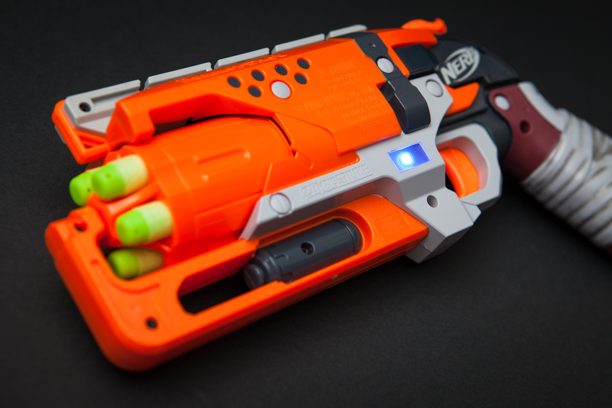
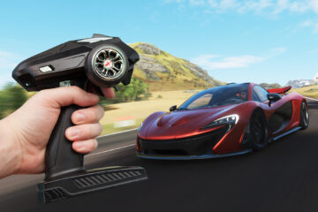
I’ve always been fascinated by RC cars. The dynamics, the engineering, the speed… all wrapped up in a package that you can hold in one hand. Almost more than the cars themselves I’ve always loved the remotes. Ever since I watched Back to the Future and saw that awesome modded Futaba remote I’ve been captivated by the possibilities contained in one of those mystical black boxes. I was playing a racing game the other day when the idea came to me: what if I could modify an RC controller to control a racing game?
And just like that, I decided to convert an RC controller into a gamepad to play Forza Horizon 4.
(more…)