I’ve always been fascinated by RC cars. The dynamics, the engineering, the speed… all wrapped up in a package that you can hold in one hand. Almost more than the cars themselves I’ve always loved the remotes. Ever since I watched Back to the Future and saw that awesome modded Futaba remote I’ve been captivated by the possibilities contained in one of those mystical black boxes. I was playing a racing game the other day when the idea came to me: what if I could modify an RC controller to control a racing game?
And just like that, I decided to convert an RC controller into a gamepad to play Forza Horizon 4.
Video
For a quick overview of the project and some footage of it in action, watch the YouTube video (and subscribe, please!). Otherwise, keep reading!
The RC Controller
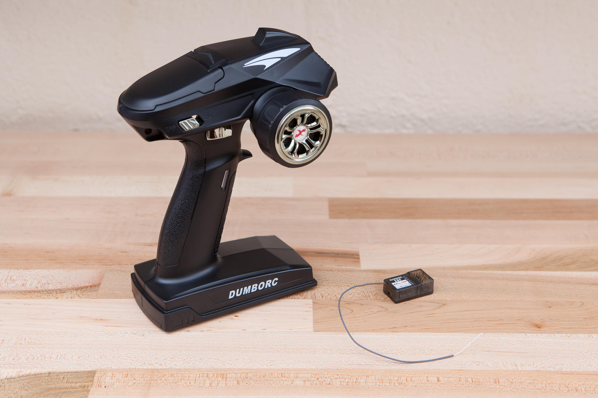
The remote for this project is a 2.4 GHz “DUMBORC X4” controller that I found on Amazon, and came packaged with a 6-channel “X6F” receiver with PWM outputs. I knew from the beginning that I wanted a “gun” style controller; a two-joystick remote seemed too similar to a traditional gamepad. This fits the bill swimmingly. In addition to the typical steering wheel and bidirectional throttle controls, the remote also has a toggle button on the grip and a three-way slide switch that’s activated by your thumb.
Despite its low price tag, the remote seems to be quite well built and has all of the features needed to make this project work.
4 CH vs 6 CH
The controller set comes in two variations: the 4-channel version I have and a 6-channel version (X6) which is slightly more expensive and adds two rotary potentiometers to the top of the controller. The 6-channel version of the controller also comes with an upgraded receiver (X6FG) that includes an integrated gyroscope.
Other than that, the 4-channel and 6-channel controllers are identical in every way: same outer casing, same mainboard, same daughterboards, same signals, same outputs. This means also means that I can use the 4-channel remote as a six channel remote – all I need to do is add some extra inputs!
Inputs and Outputs
The remote has two options for power: either four AA batteries (1.5V * 4 = 6V) or a lithium battery pack through a two pin connector in the battery compartment. The battery voltage then runs through a 3.3V regulator to power the digital circuitry and input potentiometers.
For each channel on the controller, the onboard microcontroller reads the voltage on the respective signal wire and sends it wirelessly to the receiver. The receiver then translates that voltage level into a PWM signal to control a servo motor, with an 860 to 2140 microsecond duty cycle at a frequency of 50 Hz. With this controller the voltages map linearly: 0V on the input maps to a short duty cycle, 3.3V maps to a long duty cycle, and 3.3V / 2 maps to a duty cycle directly in the middle of the range.
Of the six available channels on the controller, all six are analog inputs. This means that even the digital inputs like the toggle button on channel 3 and the slide switch on channel 4 run to the ADC pins on the microcontroller and can be rewired to use analog controls. This might come in handy…
Receiver
The controller comes bundled with a 2.4 GHz wireless 6-channel PWM receiver (X6F). The receiver has 0.1″ 3-pin headers to attach up to 6 servo motors, one for each channel. According to the documentation the receiver supports input voltages from 4.8V to 10V and consumes 30 mA.
Both the “X6F” and “X6FG” receivers have the same circuit board and outer casing. The X6FG version includes an additional IMU IC that adds the gyroscope functionality. This IC pad is unpopulated on the X6F.
Controller Disassembly
Let’s get started by taking this controller apart.
The controller body is made up of two injection molded half-shells that are screwed together. The first step is to remove the components which attach to both halves, starting with the plastic flap covering the steering and throttle calibration settings. After pulling firmly outwards and then back on the right hinge it will slip free from the mounting holes and off of the controller.
Next, the battery compartment cover needs to be slid off. Above it is a long FCC ID sticker (“2ATHVDUMBORC”). This sticker needs to be either cut in half along the center seam or peeled off entirely.
On the back of the remote there are 10 thread-forming screws holding the shell halves together. The screws have a 3 mm major diameter and are about 7.5 mm long each. These can be removed with a #1 Phillips screwdriver.
At this point the rear shell can be opened and removed, exposing the remote’s internals. Thankfully there are no electrical connections to the back half of the shell so no wires need to be disconnected.
The connectors used throughout to attach the mainboard to the peripherals are JST PH series, rectangular connectors with a 2.0 mm pitch. The housings and crimps can be purchased from the usual places.
Channel Input Breakdown
With the controller disassembled, it’s time to change around some of the existing controls and make improvements so that this remote will work better as a game controller.
Channel 1: Steering (Unchanged)
Channel 1 is connected to the “steering wheel” on the front of the controller. Turn left to increase the voltage / duty cycle, turn right to decrease it. This input has a return spring to hold the wheel at center when it’s released.
This is also affected by the left-side “calibration” controls under the top cover. The operator can set both the center trim (top pot, -3 to 3) and and the output range (bottom pot, 0 to 100). They can also invert the output direction/angle using the toggle switch.
Note that this output is “reversed” from what you would expect – turning clockwise decreases the output instead of increasing it. This is because of the steering rack geometry on RC cars. The adapter will flip this channel’s data once it’s read.
Channel 2: Throttle (Unchanged)
The throttle trigger is connected to channel 2. Pull the trigger to increase the servo angle, and push on it to decrease the angle. Like with the steering control, this has a spring to hold the trigger at a neutral position after it’s released. Similarly this channel can also be calibrated and inverted using the right-side controls under the top cover.
Channel 3: From Toggle to Momentary
The channel 3 control is a micro button that sits beneath the ring finger on the user’s left hand. Pressing the button once will turn the input and the corresponding LED on, and pressing the button again will turn it off. Holding the button, in either state, has no effect past the initial press.
I’m sure this is great for remote-controlled vehicles, but it’s terrible for a racing game. In a game you want to be able to activate inputs quickly and intuitively, not mash a single button twice in order to activate and then deactivate a control. This is particularly problematic because there’s no tactile feedback – you don’t know the state of the button unless you look at it or remember the previous setting.
With the controller apart, the first order of business is going to be converting this toggle button on channel 3 into a momentary button. That way when you press it it’s pressed, and when you release it it’s released. Just like you would expect with any other game controller.
The Momentary PCB
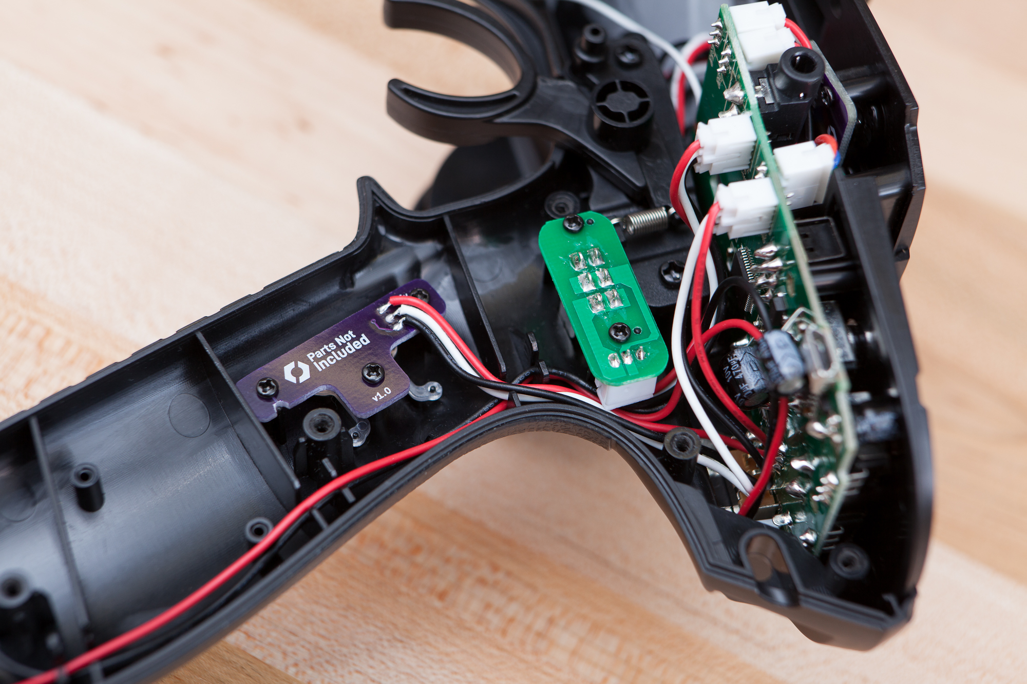
To be honest I anticipated that this would be trickier than it was. Before I opened up the controller, I imagined that the daughterboard for the button would be just the button and an LED, and the “toggle” functionality would be part of the main microcontroller’s firmware. Instead it’s the other way around – there’s already a mini microcontroller on the daughterboard! This means that instead of building a man-in-the-middle system to detect and modify the button’s output signal, all I need to do is replace this circuit board with a plain old button.
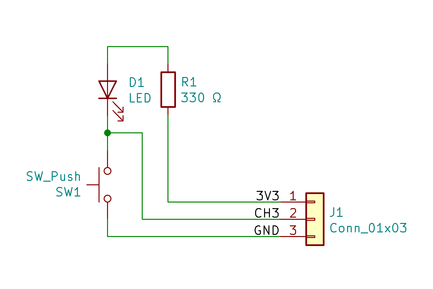
Without the daughterboard connected there’s a pull-up present on the mainboard that holds the signal line high. I decided to take advantage of this, and my replacement daughterboard only has the button, a blue LED, and a current limiting resistor for that LED. When pressed the button grounds the LED and signal wire, driving the input low.
The only consequence of using the built-in pull-up is that the output is inverted: the pulse duration is long when the button is unpressed, and short when the button is pressed. If the output was connected to a servo it would move in the opposite direction to the other servos once the button was pressed. But since I’m reading the output with a microcontroller it doesn’t make a difference.


I started by creating a CAD model of the existing PCB, including the board outline, mounting holes, alignment holes, and relevant component positions. This CAD model was then translated into DXF and imported into KiCAD to form the base of the new PCB. The button and LED were placed to match their original positions and the resistor just out of the way. After a few quick traces and some silkscreen art this was sent off to OSH Park for fabrication.
After getting it back I hand-soldered the components and installed it into the handle, re-using the wires from the original PCB. The new board is a perfect fit and no modifications to the controller grip were required. (And by “perfect fit” I mean I forgot to include drill points for the alignment holes and the endmill routing radius was too large to mill them, so I had to file them myself.)
And now the grip button is momentary!
Channel 4: 3-Way Switch (Unchanged)
The channel 4 control is a 3-way slide switch that rests under your left thumb. The switch is double-pole double-throw (DPDT), on-off-on – which is just a technical way to say that it’s a switch that has three positions: ‘on’ for output 1 (3.3V) and the signal common, ‘off’ in the center (1.65V by the mainboard pull-ups), and then ‘on’ for output 2 (GND) and the signal common. Even though this is a double-pole switch, it’s being used here as a substitute for a single-pole with both sets of poles tied together.
Unfortunately for us there’s no digital controller input for Forza that needs to be “held” like this except for the throttle – most are momentary inputs to trigger an action. So rather than fiddle with setting and resetting this finicky switch, I’m going to replace it with a momentary one!
At least, that was the plan.
Supply Issues
As it turns out, unlike the ubiquitous momentary button, momentary slide switches aren’t a widely manufactured part. At least not three-way slide switches in the size that I need.
I was looking for either “On-Off-Mom” or “Mom-Off-Mom” switches, meaning momentary contact (return spring and no detent) in either one or both directions. I found a handful of these switches, but they were all either too small or too large to fit into the cavity above the channel 4 PCB in the controller’s handle. They also had handles which were either too short or too thin to attach to the switch cap without an adapter.
So rather than build a custom PCB, a custom mounting bracket, and a custom extension cap to mount to the existing switch cover, I decided to ditch the concept altogether. Instead I’m keeping the existing switch and I’m going to repurpose it as a “mode select”, where the absolute positioning is actually beneficial.
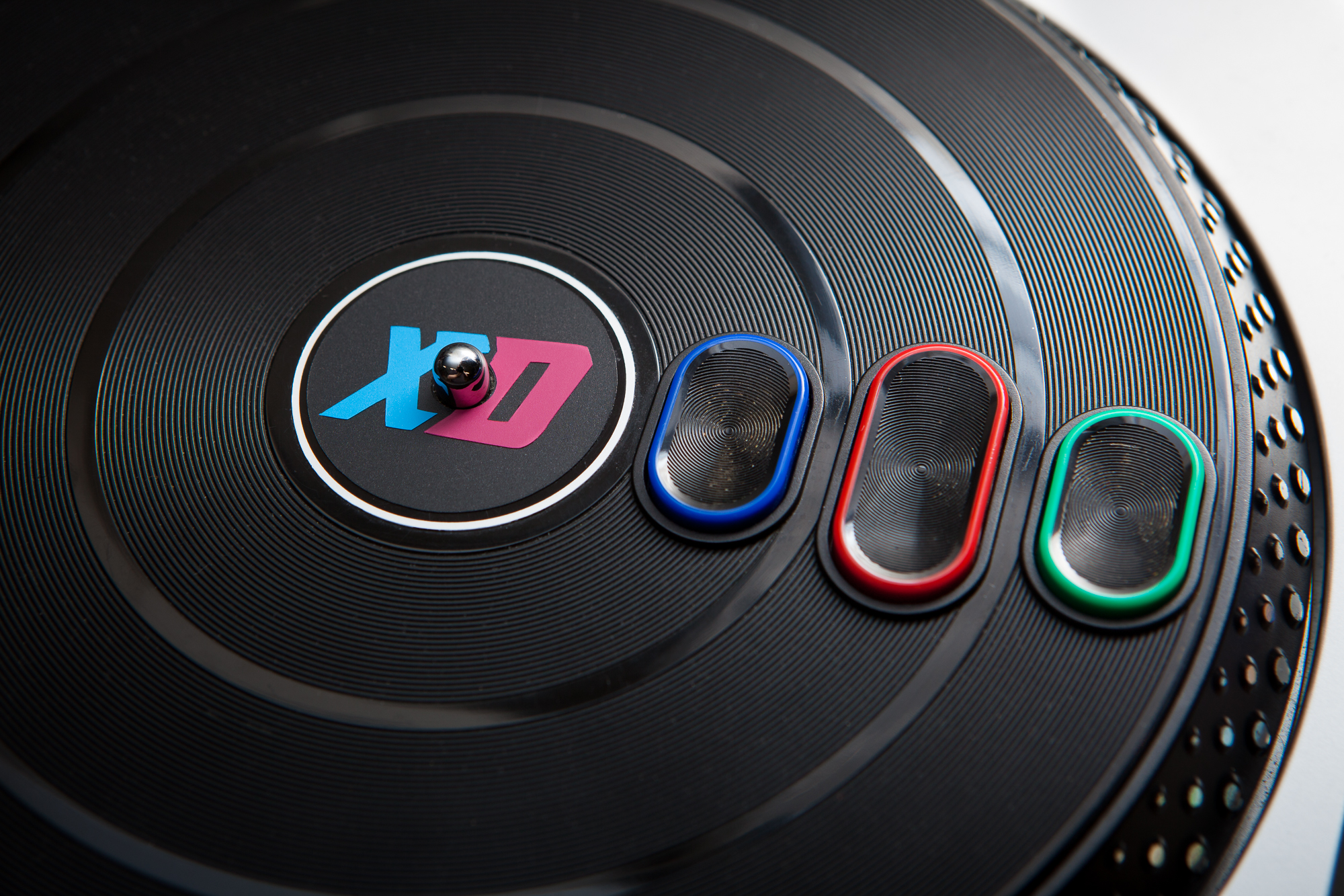
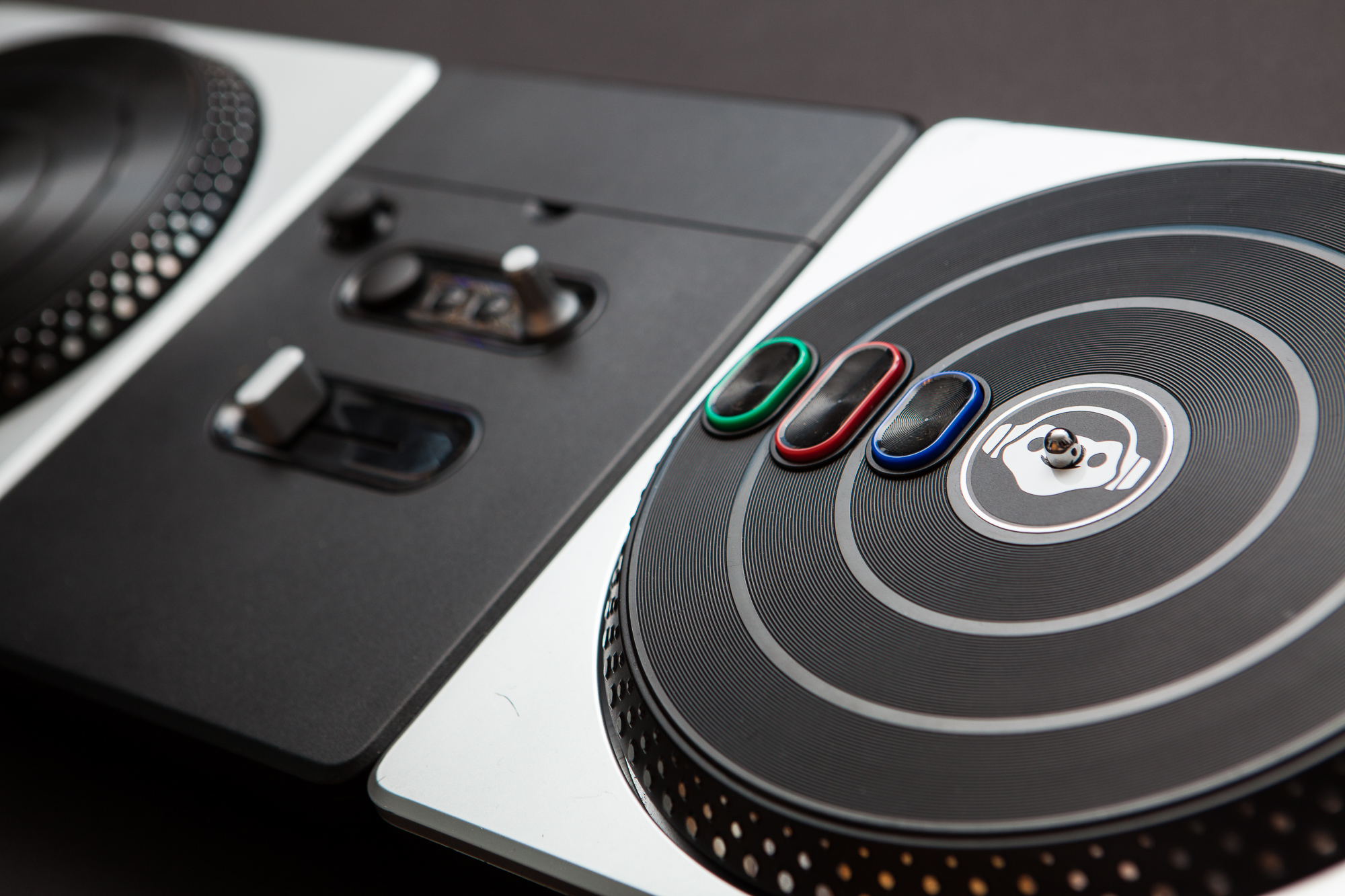
Channel 5/6: Adding Buttons
Here’s where things get interesting. When I purchased the remote I noticed that there were two versions available: a “4-channel” version with the toggle button and three-way switch, and a “6-channel” version for a few dollars more that adds two potentiometers which stick out from the top. These absolute potentiometers aren’t great for games, but I can repurpose the ADC inputs as generic digital buttons.
Mounting and Button Holes
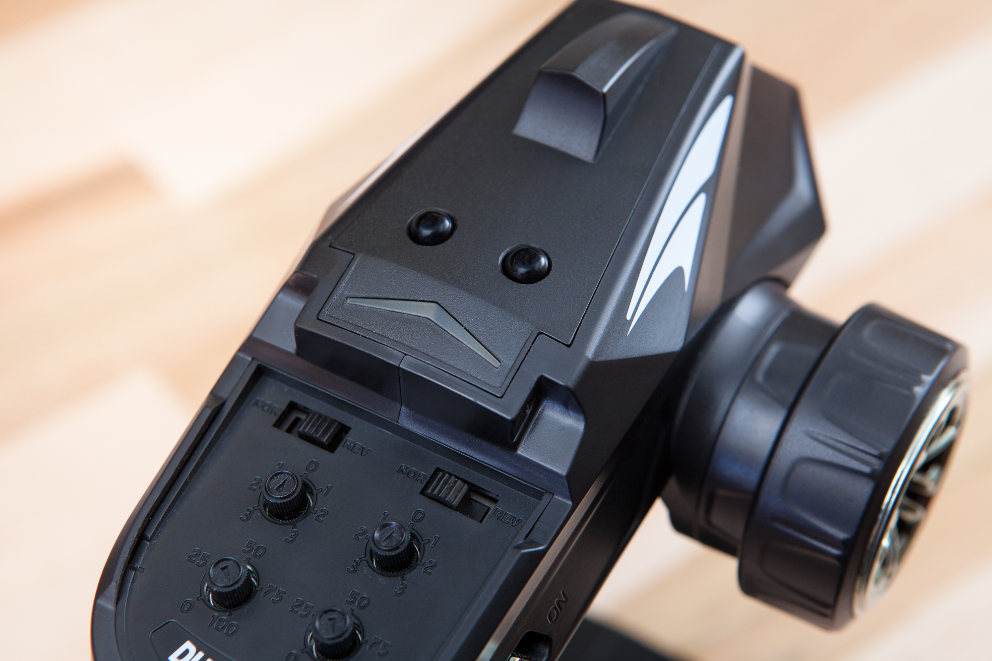
I lucked out here. Even though I’m using the “4-channel” version of the controller, both versions share the same interior injection mold for the top cover. This means that while the top cover on the 4-channel version is smooth, the underside includes three mounting posts (with alignment pins!), and two circular bosses surrounding the would-be holes for the potentiometers. Score!
To make this work for buttons, I just need to drill out the holes where the potentiometers usually sit. I did this using a 1/4″ drill bit by hand (literally, holding the bit in my hand). The ABS plastic is soft and thin, and I didn’t want to risk having the bit go sideways by using a power tool. It only took a minute until the bit was through the plastic and the hole was cleared.
Once both holes were through the top surface, I put the bit in a cordless drill to round off the excess and then used a small needle file to clean up the edges. To prep the holes for the buttons I wrapped some 600 grit sandpaper around a drill bit and rubbed it up and down through the hole to smooth out the bore. Last but not least, I chamfered the tops using an 82° countersink.
Note: While I could have used the 6-channel version of the controller, I actually wanted the 4-channel version because a straight-through hole is better for the buttons than the counter-bored hole on the 6-channel version of the controller. This is because the caps I’m building are going to be retained from the inside and wouldn’t be able to fill the counter-bore from the top.
The three screwposts are the same size and shape as the ones for the channel 3 and 4 PCBs, so I ordered some cheap M2 x 6 self-tapping screws to attach the PCB to the case.
From Potentiometer to Button
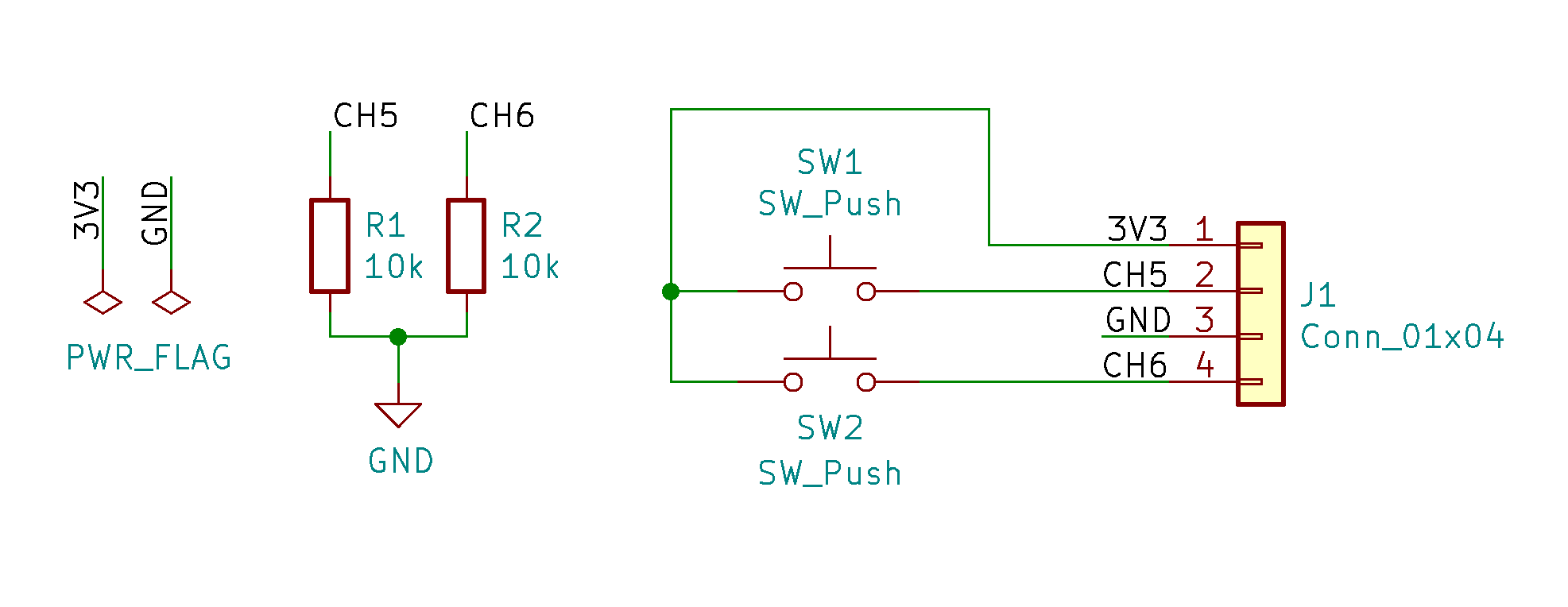
As with the channel 3 PCB, I started the circuit making process by inspecting the internals and the existing connections on the mainboard. It looks like both inputs for channels 5 and 6 have an RC filter on the mainboard but otherwise the signal lines are left floating. This makes sense, because you can see the output levels on the receiver roughly follow the signal for channel 1 when a wire (i.e. antenna) is attached to the signal wire for either channel.
This is lucky because it means the button circuit is dead simple: pull-downs on the signal lines, and momentary buttons that connect the signal lines to the ‘high’ voltage (3.3V).
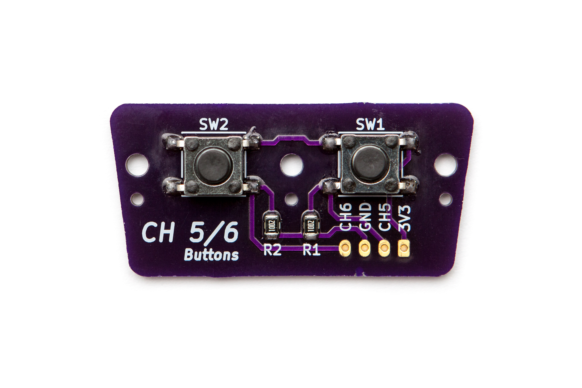
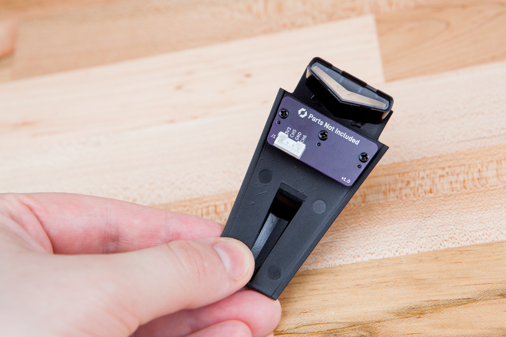
There’s not much to say about the PCB itself. The shape is trapezoidal to follow the narrowing angle of the top plastic cover to which it mounts, and has three mounting holes for screws and alignment holes to attach to the existing posts. The buttons were placed directly underneath the hole bosses to the best of my measurements, although because I’m drilling these out by hand they may not match perfectly.
The final PCB was ordered from OSH Park and hand soldered. To connect it to the mainboard I added a 4-pin JST PH connector and built a matching cable using 26 AWG wire.
Making Button Caps
The final step for these channel 5/6 buttons is to make some small plastic caps so that the buttons will stick through the top of the enclosure.
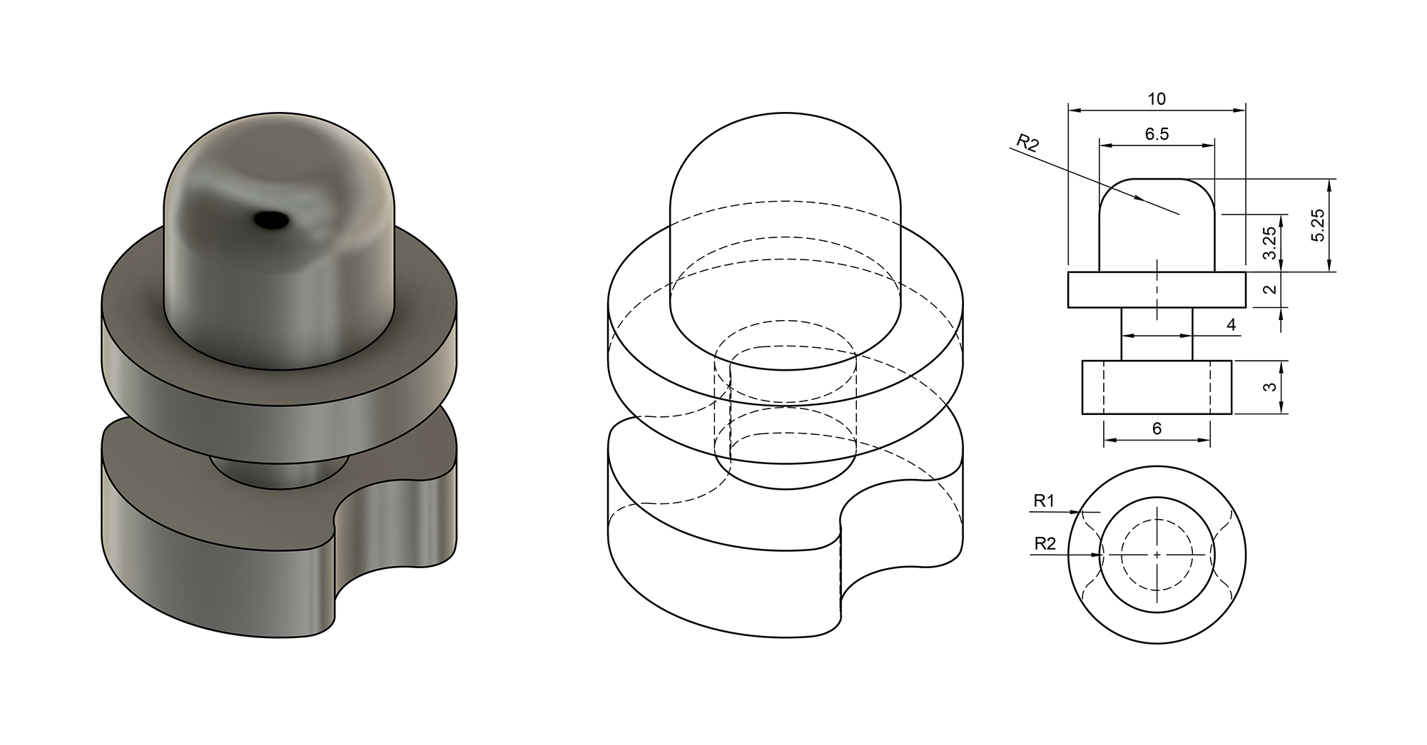
The design I came up with is radially symmetrical with a flange on the bottom to keep the button retained inside of the controller, sandwiched between the plastic cover and the button on the PCB. Because the buttons I’m using have a very short stroke (actuation distance), these are sized so that the height only sticks up slightly above the surface of the cover.
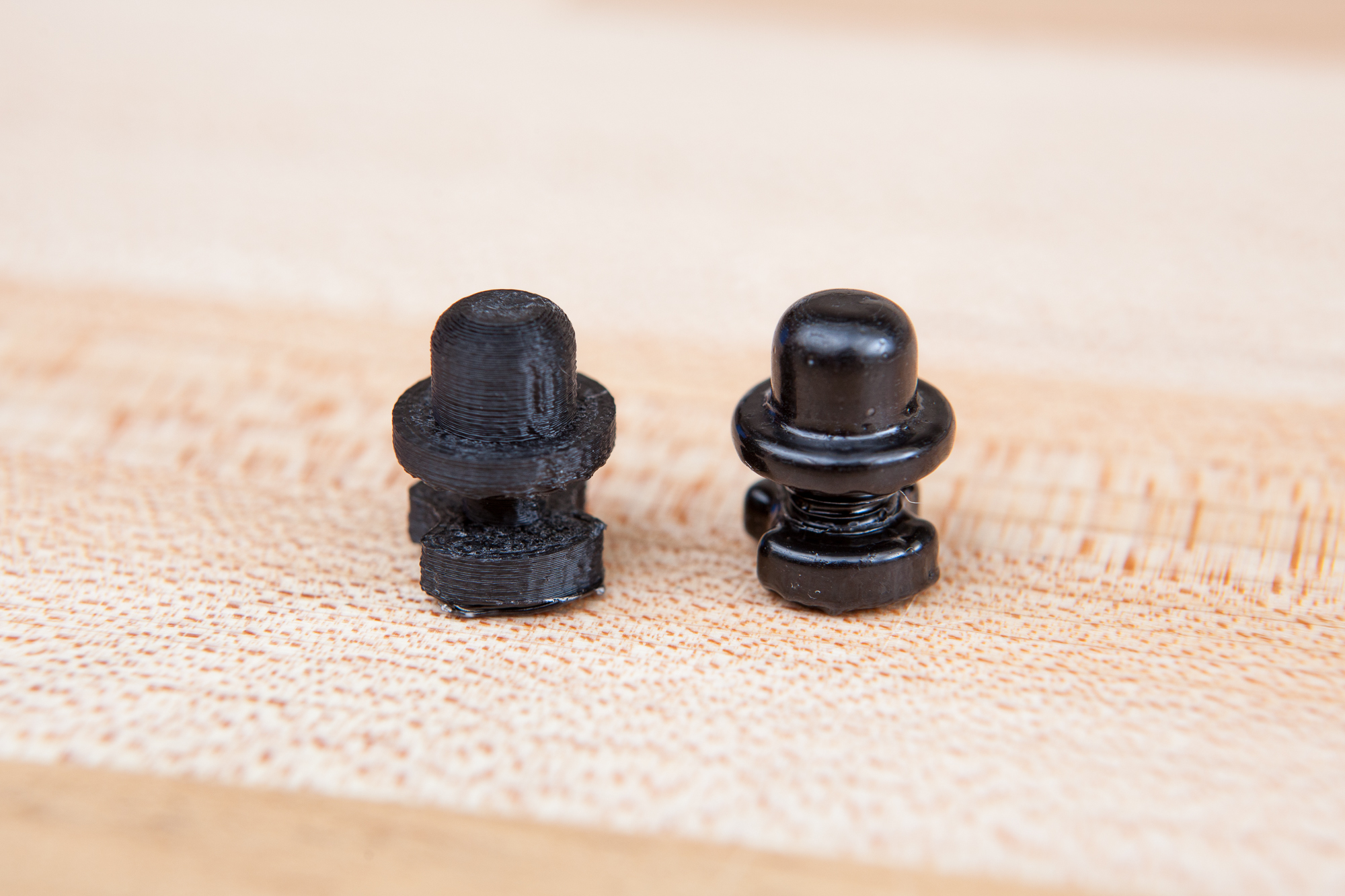
In an ideal world this is the perfect lathe part – just some 3/8″ Delrin and 10 minutes on a lathe would get you a pair of perfectly symmetrical caps polished to a mirror shine. Unfortunately I don’t own a lathe of any sort at the moment, so I’m going to make these in a rather hack-y fashion using my 3D printer and acetone vapor smoothing. Don’t try this at home.
I extended the design to include a small stem and a “plug” on the end so that I could wrap a wire around the part, with small scallops so that the hanging wire could lay closer to the centerline. After printing at 100% infill out of ABS, I suspended the caps one at a time in a small glass jar of acetone on top of a hot plate running at 130° C. I left these to smooth for 15 minutes, then transferred the caps to a hanging line to dry and harden. 48 hours later I had a collection of mostly smooth buttons.
After selecting the two best looking caps, I snapped off the hanging “stem” with a pair of side cutters and then sanded the underside until the cap fit snugly between the PCB and the plastic cover. The channel 5/6 PCB was then securely screwed into place and connected to the mainboard using my custom cable.
And now we have two extra buttons to play with!
The USB Receiver
That should be all of the hardware needed on the controller side, so now let’s turn our attention to the other half of the project: the USB microcontroller that’s converting our tweaked RC inputs into a game controller.
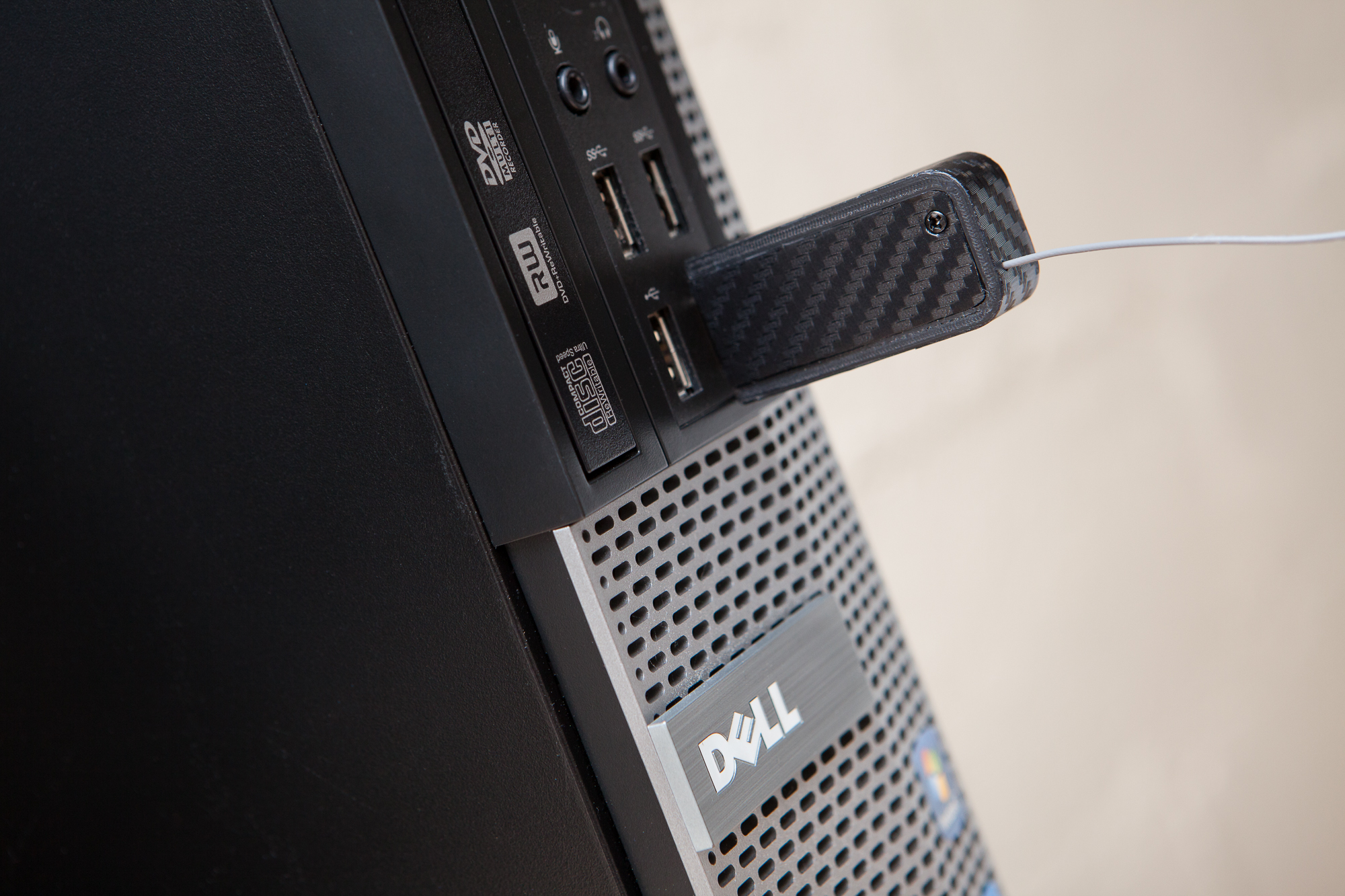
My goal for the receiver was to create a pluggable “dongle” like a WiFi adapter or USB flash drive that could just be inserted directly into a computer without the need for a cable. Like my other controller projects I also wanted this to be truly “plug and play”, meaning no extra configuration or setup required on the PC.
The Microcontroller
To make this a “dongle” I needed a microcontroller with a built-in USB-A port that I can connect directly to a computer without using a cable. I couldn’t find any that fit the bill, so I decided to build my own based off of a SparkFun Pro Micro. See the article on that project for more information.
The Pro Micro uses an Atmel ATMega32U4 for its brain. The 32U4 is based on the AVR architecture and is Arduino-compatible, being the same microcontroller used in the Arduino Micro and the Arduino Leonardo. Most importantly for this project, this microcontroller has an onboard USB controller and is compatible with my Arduino XInput library which will allow it to emulate an Xbox 360 controller. It also offers 5 external interrupt vectors for the PWM channel inputs, the sixth of which will be handled by a pin change interrupt.
Disassembling the Receiver
The RC receiver comes in a small plastic case with offsets to account for the height of the 0.1″ servo pin headers. The case is held together with plastic clips along the long edges that can be opened with a plastic spudger.
Since I’m running wires directly to the signal pins I don’t need the tall 0.1″ headers, so they need to go in order to get the size down. There are 18 pins in total: six rows of three pins each. These are all connected by a plastic spacer so they act as one “block”. Before desoldering them, I used a hacksaw blade to carefully split the columns and then a side cutter to separate each pin. For the desoldering itself I heated up and removed each pin one at a time, then went back over with a solder sucker to remove the excess. For good measure, I also cut off the 16V 100 uF electrolytic cap to save another quarter inch of space. This cap shouldn’t be necessary since we’re not driving any servos.
I was a bit aggressive with the desoldering since I was initially trying to avoid the hacksaw, and ended up removing one of the signal pads and lifting the others slightly. Thankfully everything still works and I can use the pad on the other side of the board.
Making the “Sandwich”
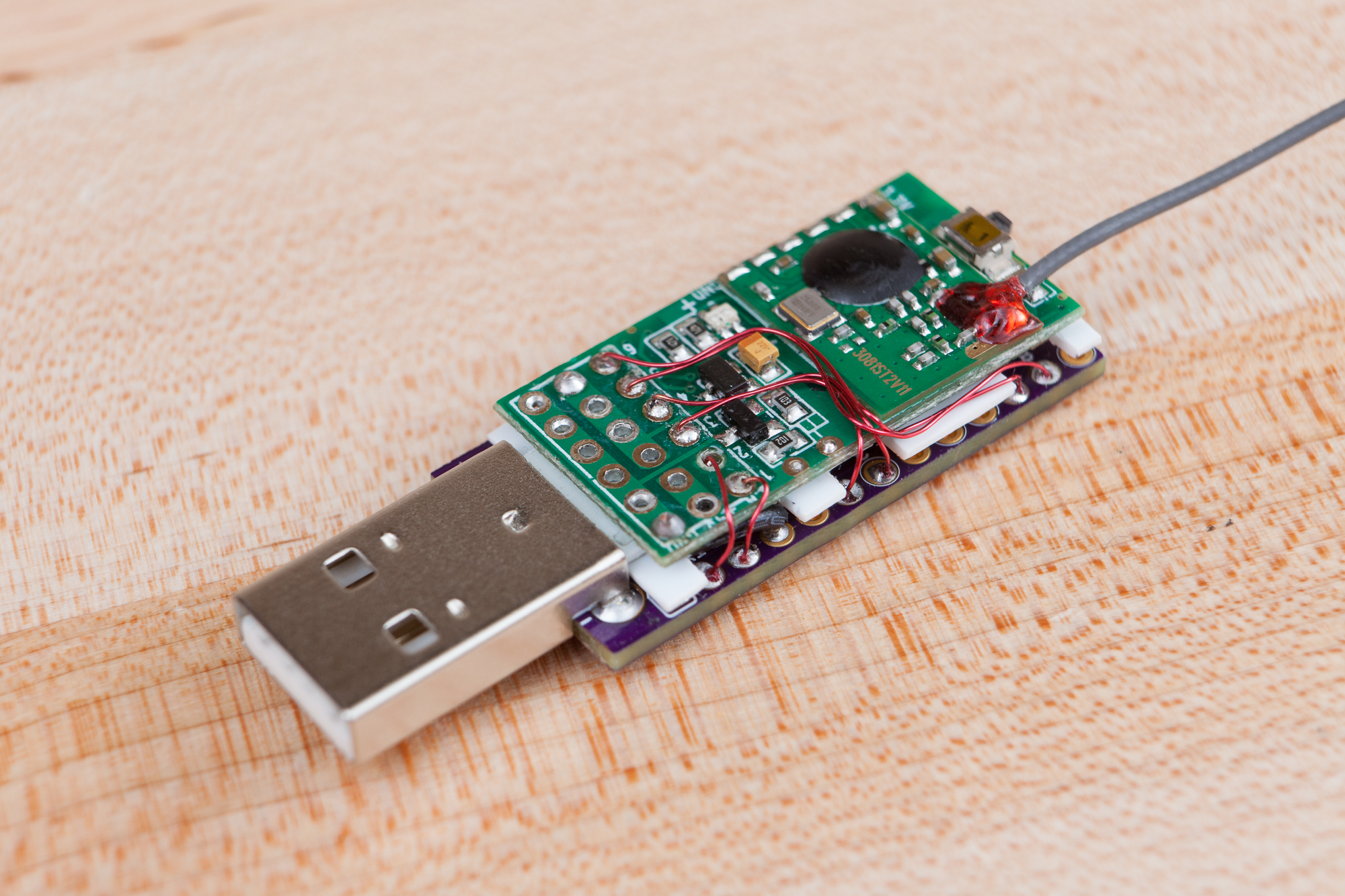
In order to fit inside of the smallest area possible I decided to “sandwich” the microcontroller and receiver boards together one on top of the other. With the header pins gone, the PCB for the receiver is about 3 mm tall, 16.35 mm wide, and 31.25 mm long. This makes it the perfect size to piggyback on top of the USB-A Pro Micro, whose area behind the USB connector measures 17.78 mm (0.7″) wide and 33 mm long. As the USB port adds a solid ~3.3 mm to the height of the Pro Micro, it only made sense to put the receiver on the top of the board and maintain the flat bottom.
There are two wrinkles to this plan. First, both boards have components on them so the adjoining faces aren’t flat. Second, the mating faces on both boards have SMD parts with exposed leads, which could result in shorts. My solution to both of these problems is to make a styrene sheet “cheese slice” to act as a buffer between the two boards.
The tallest components on the Pro Micro are the tantalum capacitors, and the second tallest component is the microcontroller itself. The difference between these is 0.030″, which is exactly the thickness of the styrene sheet I have on hand. I cut a sheet to size, made some cutouts for the caps, and sealed the holes with a small piece of kapton tape. The board sandwich was then finished using small pieces of double-sided tape between each part: Pro Micro, styrene, then receiver in that order.
Soldering Interconnects
The last step to finish off the receiver and Pro Micro sandwich is to add the electrical connections between them. There are eight connections in total: power, ground, and the six servo channel signals. All receiver connections were soldered before the receiver was adhered to the polystyrene isolator, and all Pro Micro connections were soldered after.
| Ch | Pin | Port | Vector |
|---|---|---|---|
| 1 | RX1 | PD2 | INT2 |
| 2 | TX0 | PD3 | INT3 |
| 3 | 2 | PD1 | INT1 |
| 4 | 3 | PD0 | INT0 |
| 5 | 7 | PE6 | INT6 |
| 6 | 8 | PB4 | PCINT4 |
I split the power and ground connections between the left and right sides of the board, to the RAW and GND nets respectively. For these I used short pieces of 22 AWG solid-core wire. The hope is that the stiffness of the solid-core wire will help the double-sided adhesive hold the receiver in place.
For the signal connections I decided to do something new and use some enamel wire, also known as “magnet wire”. Compared to your typical insulated wire, enamel wire uses a thin enamel coating instead of a separate insulated sheath. This means it doesn’t require stripping and it’s considerably thinner for the same wire thickness.
I picked up some 30 AWG magnet wire from Amazon for this. After burning off the enamel on the tip of the wire, I soldered ~6″ to each channel coming up through the top of the receiver. Once the power connections were soldered I used a toothpick to help bend the enamel wire, guided it through the pins of the Pro Micro, then soldered it into place. I didn’t bother removing the enamel for the microcontroller connections, just let the iron linger a bit longer to burn it off.
Signal channel connections were made to the five pins on the Pro Micro that support external interrupts, plus one additional pin that’s used with pin change interrupts (8, i.e. PB4). Connections were made in increasing order with the exception of channels 1 and 2 which were reversed to simplify the routing.
After all of the connections were complete I double-checked continuity with a multimeter, then plugged it in to USB to check that the microcontroller was receiving the servo signals. All systems go!
Making a Case
The final step to finish the receiver is to make a case. The purpose of the case is to keep everything self-contained and protect the connections from being disturbed.
Initially I considered going with the quick and dirty solution of making a box and coating everything in potting epoxy, but I eventually decided against this because it locks me out of fixing any issues. Most significantly, it would prevent me from reprogramming the board via the SPI interface if I accidentally upload bad firmware over USB.
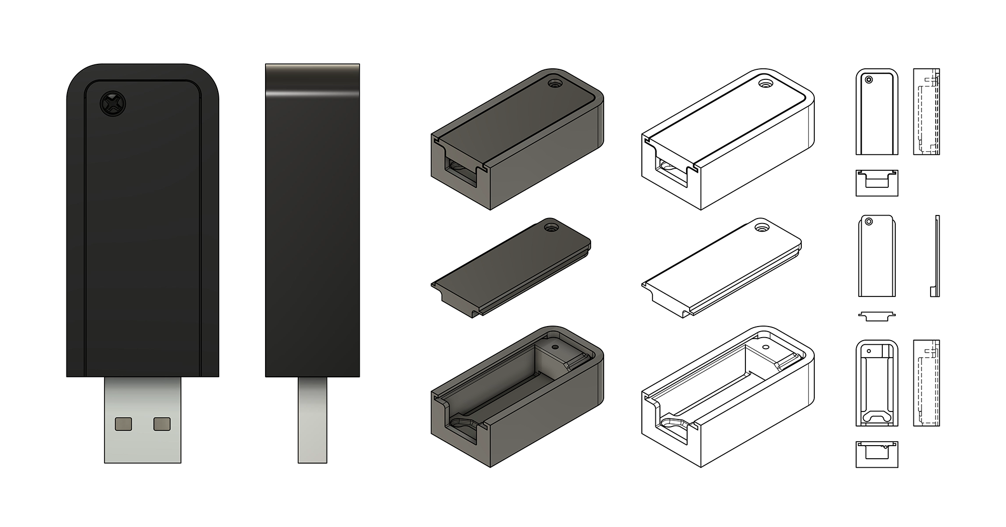
What I ended up with was a two part 3D printed case. The bottom half includes cutouts for the pins on the bottom of the microcontroller, as well as a clearance hole for the receiver antenna and cutouts for the cover. The cover slides in from the ‘front’ (USB-side) and includes a small boss to block out the area above the USB connector. It’s then retained by a single M2-6 thread-cutting screw that drives directly into a hole in the bottom half of the case. The microcontroller and receiver sandwich is inserted from the top and is a tight friction-fit against the sides of the case. Once the top cover is secure the microcontroller has no slack within the case.
The two case halves were printed out of black ABS on my Printrbot Simple Metal.
Adding Some Style
At this point the hardware for the RC controller and USB receiver is functionally complete. But the hardware isn’t 100% “done” until it has a bit of flair.
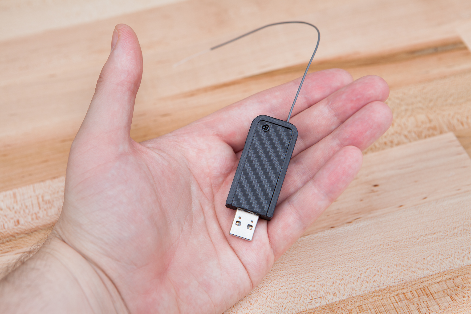
Receiver Vinyl
Let’s start with the receiver. Normally to “finish” a 3D printed part I would sand it, apply filler, prime it, and then paint it to achieve a smooth and finished look. That entire process takes a long time and right now I don’t have the patience for it. So instead I decided to make it smooth by covering the entire thing in adhesive vinyl. And what better vinyl to use for a racing controller than carbon fiber weave?
I applied a single fat ‘T’ section of vinyl across the receiver’s case bottom and sides, with cutouts to avoid the rounded corners. Next I cut a short strip to cover the rounded corners and the short side edge, and then a final piece to cover the face on the top half of the case. These pieces were cut by hand and were not measured. Once the vinyl was secured all edges were then trimmed and chamfered with a craft knife to remove any burrs. I then cut an ‘X’ through the vinyl on both holes to clear the antenna and mounting screw.
Both the ‘front’ face (where the USB port exits) and the outer ‘ring’ on the base’s top were left uncovered. Adding vinyl to these areas would have been difficult because the surface area is so small, and I quite like the added contrast.
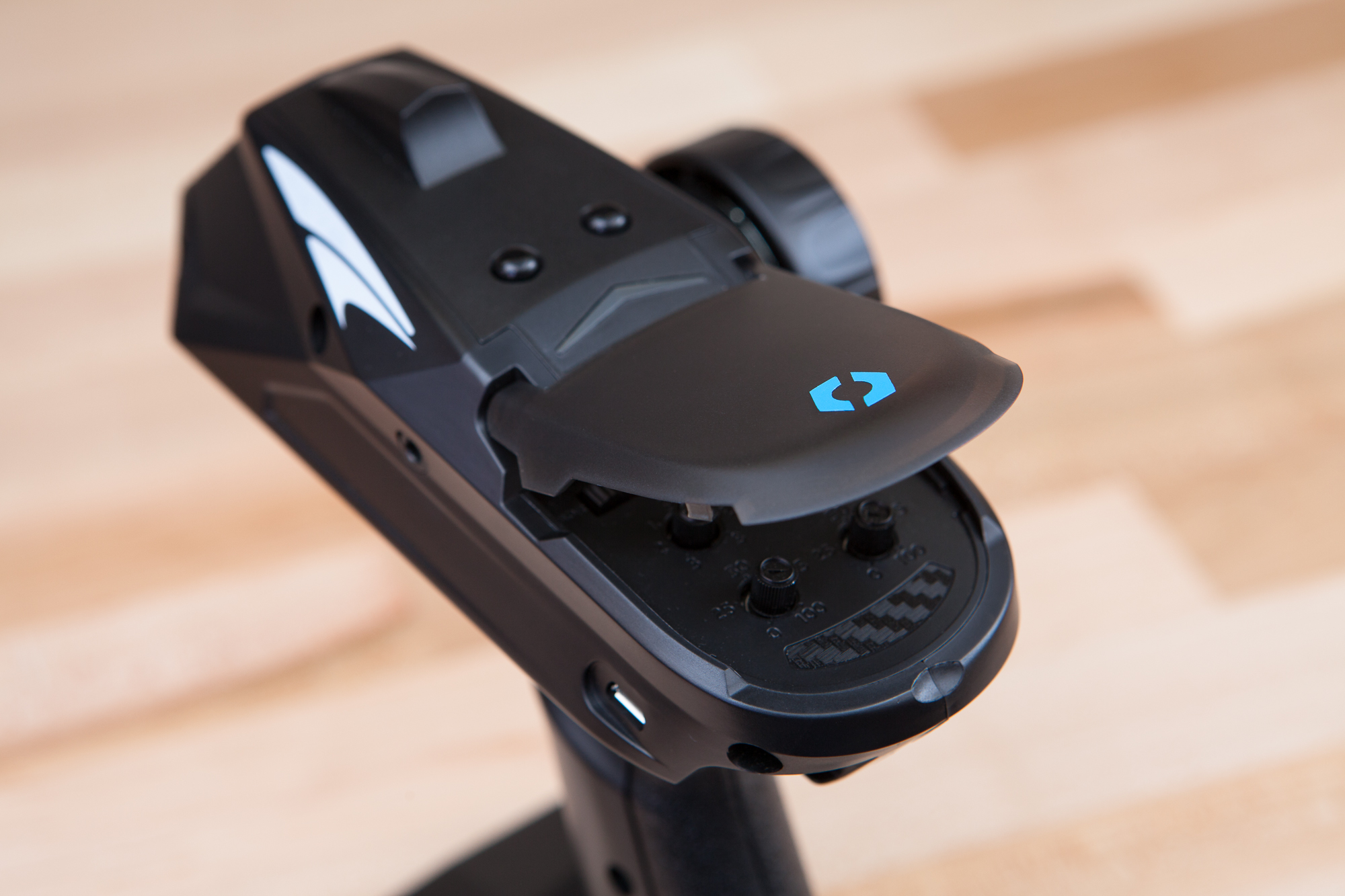
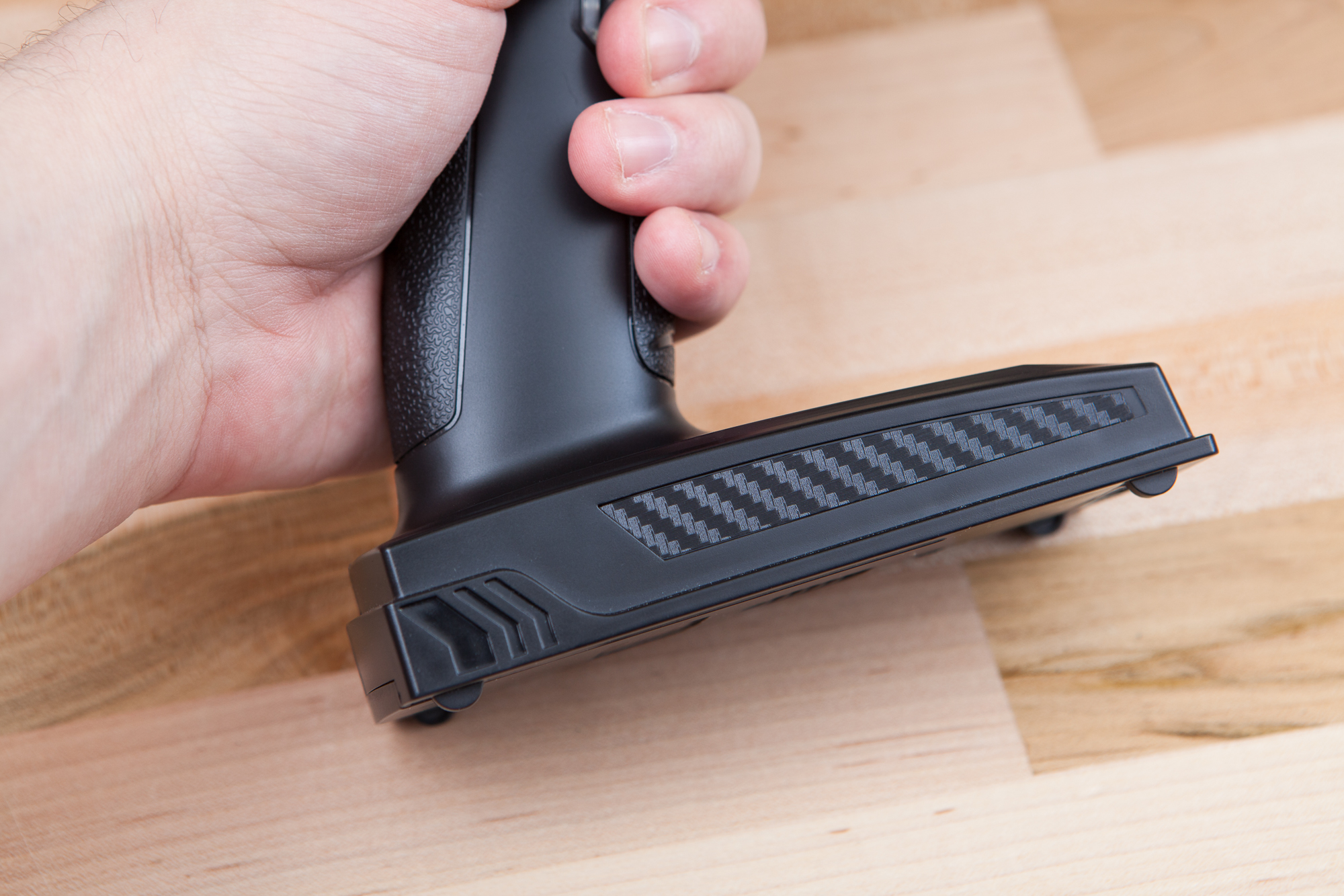
Controller Vinyl
The controller has a different problem. As the outer casing is injection molded it’s plenty smooth, it’s just covered with “DUMBORC” branding: in two long strips along either side of the base and one small alcove below the calibration controls.
While the controller was disassembled, I scanned the surfaces with the labels and used those images as reference to make matching outlines in Illustrator. Those outlines were then used to cut matching vinyl covers on my Silhouette Cameo 3.
Initially I tried using sky blue vinyl to add a splash of color, but it stuck out like a sore thumb against the muted controller surfaces. I ended up using more of the carbon fiber vinyl, which blends in nicely with the black plastic unless the light hits it at an oblique angle where it shines.
To complete both pieces, I added two 0.45″ wide Parts Not Included logos in sky blue: one on the back of the calibration cover for the controller, and one on the bottom of the receiver’s case.
Programming for Forza
With the hardware complete, the final step is to program the firmware for the microcontroller to convert our servo outputs from the RC receiver into USB gamepad inputs for Forza Horizon.
Reading Servo Inputs
The first (and most significant!) step in this process is to get the signals converted from 50 Hz PWM into a range or percentage that can be used by the microcontroller.
This is easier than you think. Each servo signal is a PWM pulse that varies from approximately 860 to 2140 microseconds depending on the prescribed servo angle (see the channel overview above). The microcontroller just needs to wait for the signal to go high and then record the duration. Or more accurately it needs to record the time the signal goes high, and then subtract the time when the signal goes low again.
This is accomplished with a CHANGE interrupt that checks the pin state to see if it’s a falling or rising edge, then records the timestamp using the built in Arduino micros() function utilizing the onboard Timer0. This function has a resolution of 4 µs, giving the controller a resolution of approximately 250 steps over the channel range:
void isr() {
	static unsigned long start = 0;

	const boolean state = *portInputRegister(digitalPinToPort(pin)) & digitalPinToBitMask(pin) ? 1 : 0;

	if (state == HIGH) // rising edge
		start = micros();
	else // falling edge
		pulseDuration = micros() - start;
}
Both this function and its associated variables need to be repeated for each interrupt vector (channel) in turn. This was getting a little messy so I ended up wrapping it all into its own standalone library: ServoInput. For each channel input, I only need to create a single templated ServoInputPin object. The object’s constructor creates the interrupt and then the channel data can be extracted through one of the many available mapping functions. The library also includes some advanced features to make this process more robust such as buffering, range rescaling, and the ability to determine whether an updated PWM signal has been read.
You can find more information about the ServoInput library in this article.
An Aside: Bootloader Reset
One problem that I needed to solve was that of the bootloader. The 32U4-based Arduinos all come with CDC serial descriptors that present it to the host as a serial device regardless of whether the USB serial interface is used or not. To reprogram the board via USB, the Arduino IDE sends a ‘reset’ signal using this port and waits for the board to jump to the bootloader and reconnect. When using the board as an XInput device this serial interface no longer exists and the board needs to be reset manually (double tap from RST to GND) in order for the upload to succeed. I didn’t want to open up the receiver’s case every time I wanted to change the code, so I wrote a special function to reset the board for me.
This function borrows heavily from the Teensy 2.0 core, which also uses the 32U4. In a nutshell, it disables interrupts, disconnects from USB, resets all of the peripheral registers (including timers and I/O pins), then performs an assembly jump to the top of the bootloader address space (0x7000)
This is linked back into the RC controller’s outputs, so the reset can be triggered directly from the controller without opening up the case. Holding all three buttons (Ch3, Ch5, and Ch6) will trigger a bootloader jump after 7 seconds. Assuming this function is always included, the case never has to be opened to initiate a manual reset.
USB Outputs and Controls
For the controller outputs via USB I’m using my ArduinoXInput library which enables the microcontroller to emulate an Xbox 360 controller (XInput). This is detected natively by the game and requires no setup on the PC.
Most AltCtrl projects don’t have the luxury of extra inputs and this project is no different. The Xbox 360 controller has six analog axes (joy XY and triggers, left/right) and fifteen buttons, while the RC controller only has two analog axes, three buttons, and one three-position slide switch. Although racing itself in Forza only requires a handful of controls, the game is feature-rich and requires the nearly the entire Xbox gamepad to navigate its intricacies.
As I wasn’t able to secure a momentary slide switch as a replacement for channel 4, I decided to use that control as a “mode” selector, and swap the other five controls around depending on the selected mode.
Race Mode
The simplest mode is ‘race’ mode. This makes the controller behave like it would when driving an RC car:
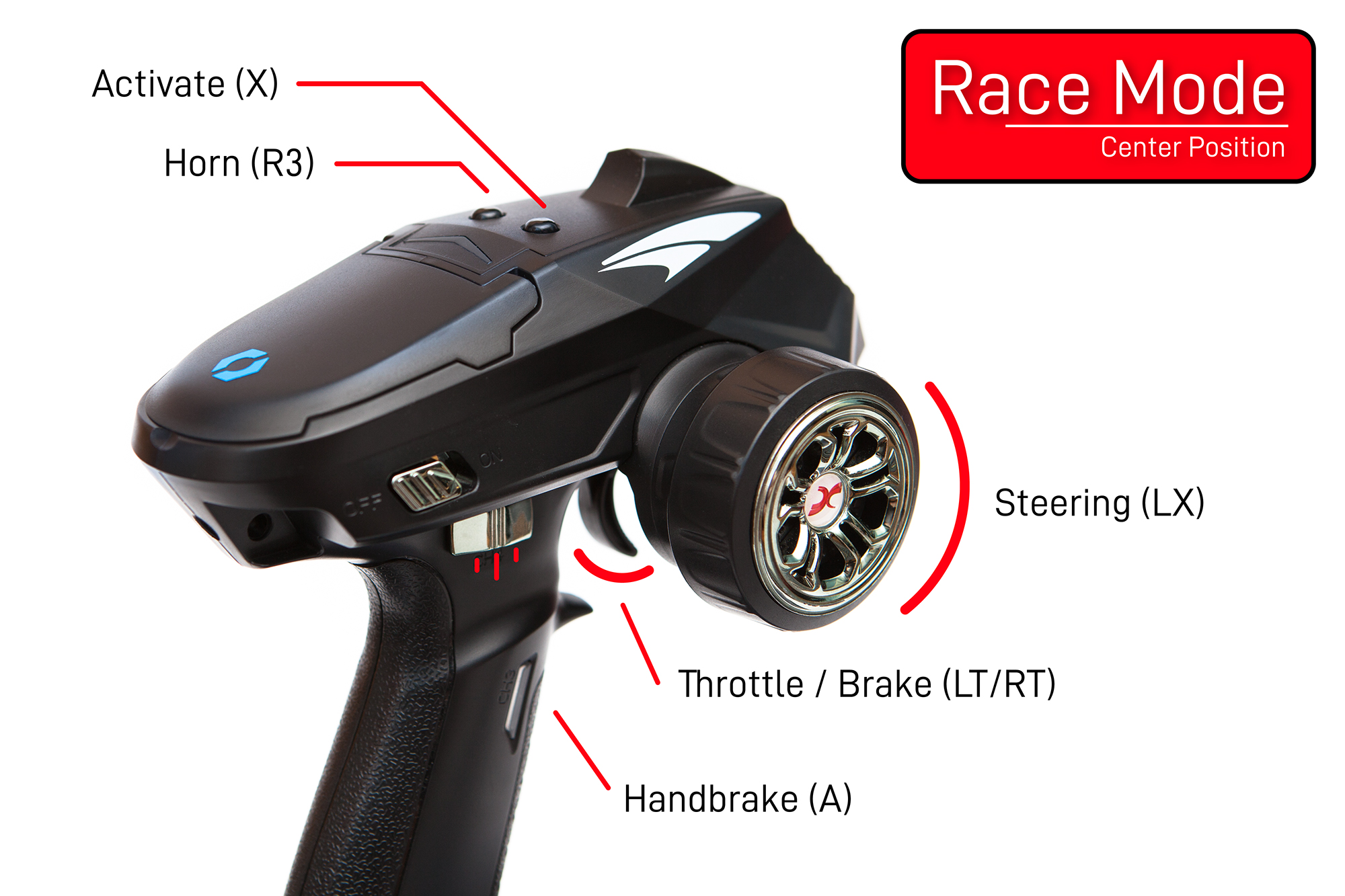
Steering controls the steering (left joystick X axis), throttle controls the throttle (trigger axis), and the grip button controls the handbrake (A). The close top button (Ch 6) enters events (X) and the far top button (Ch 5) honks the horn. A fundamental control for any serious automotive competition.
Race mode is assigned to the center position on the slide switch. This makes it easily accessible from either of the two other modes.
Menu Mode
The next mode is ‘menu’ mode. This is meant for navigating the many menus within Forza Horizon.
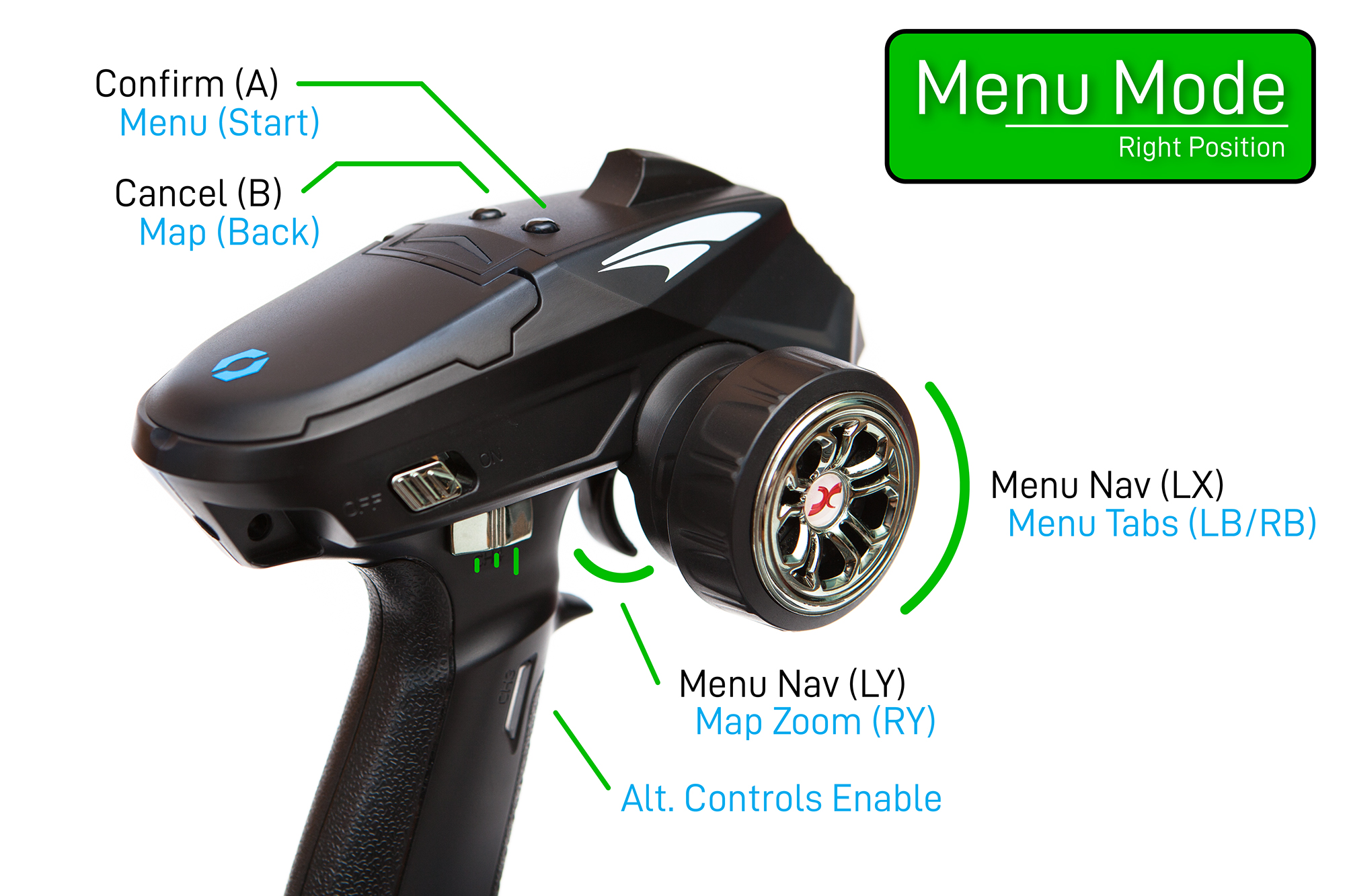
This keeps the steering control mapped to the left joystick X axis for horizontal menu navigation, but swaps the throttle control to left joystick Y for vertical menu navigation. The close top button confirms actions (A) and the far top button cancels them (B).
But this mode performs double duty. Holding the grip button enables an alternate mapping for controls that are less frequently used but still required for menu navigation. This alternate set links the steering wheel to the bumpers (LB and RB) for changing between menu tabs and swaps the top buttons for ‘start’ and ‘back’ (close and far, respectively). It also swaps the throttle from moving the left joystick’s Y axis to moving the right joystick’s Y axis. This is used for zooming in and out when using the map.
Menu mode is assigned to the right position on the slide switch.
‘Extras’ Mode
This is the “everything else” mode. After ‘race’ mode and the two mappings of the ‘menu’ mode there are still a handful of controls left unmapped:
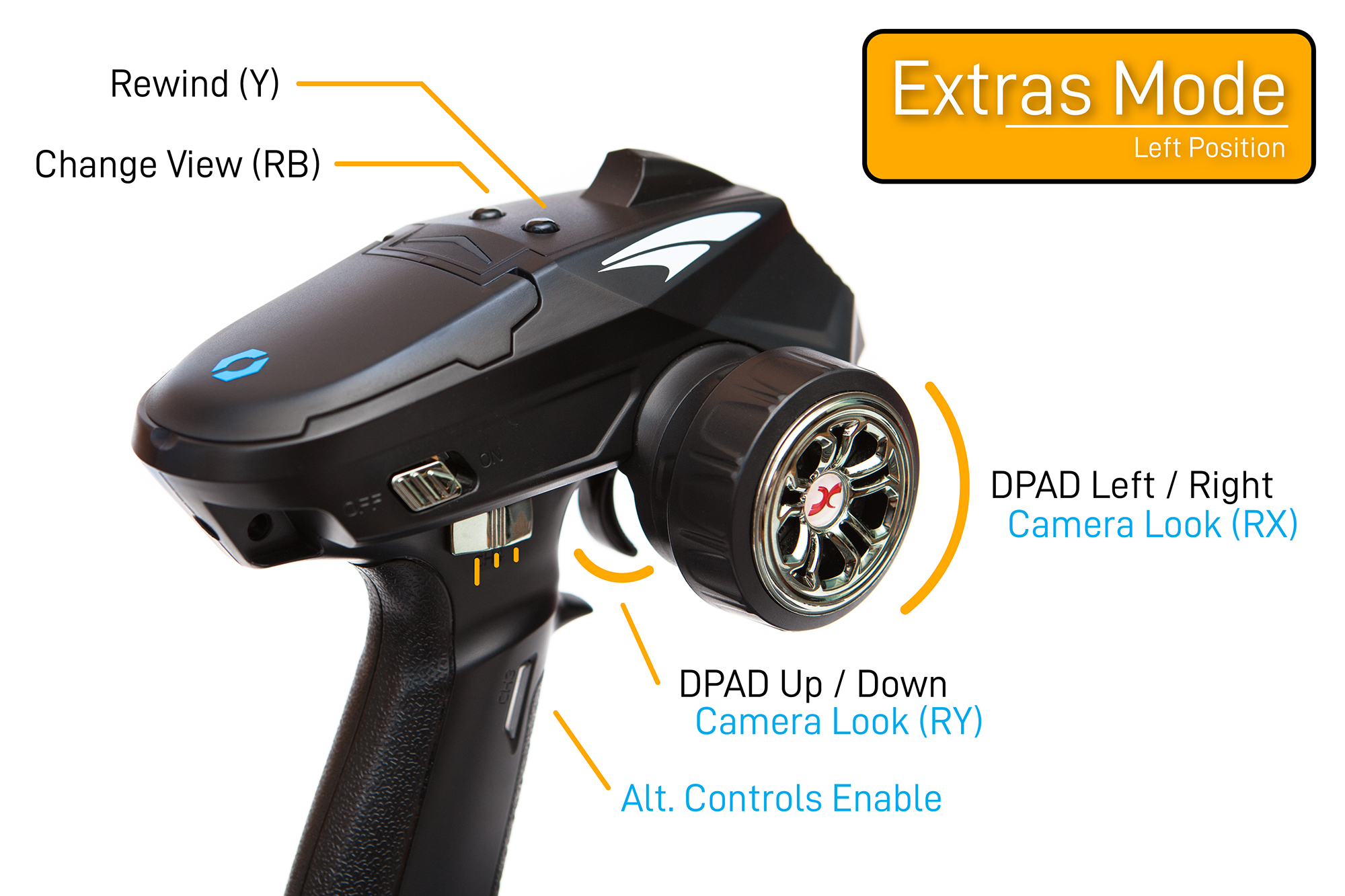
This mode takes care of (most of) these extra controls. Y (rewind) and RB (change view) are mapped to the top buttons (close and far, respectively). The steering and throttle are mapped to the directional pad for things like quick chat and changing radio stations. And pressing the grip button swaps the analog inputs to the right analog stick which is used for certain menus and for looking around the car.
The only buttons not included on the controller are the “Xbox” (center) button and the left joystick button (L3), as neither are used by Forza Horizon in the default control scheme. “Change View” (RB) in this mode is a repeat of one analog control from the Menu mode, but it seemed more intuitive to include here as well.
The ‘extras’ mode is assigned to the left position on the slide switch. If you can think of a better name please let me know!
Although these mappings are designed around Forza Horizon 4, because it functions as an Xbox controller this also works out of the box with most other racing games. I tested with Trackmania, Dirt, Burnout, Grid, and F1, but any game with left joystick steering and throttle / brake on the triggers will work.
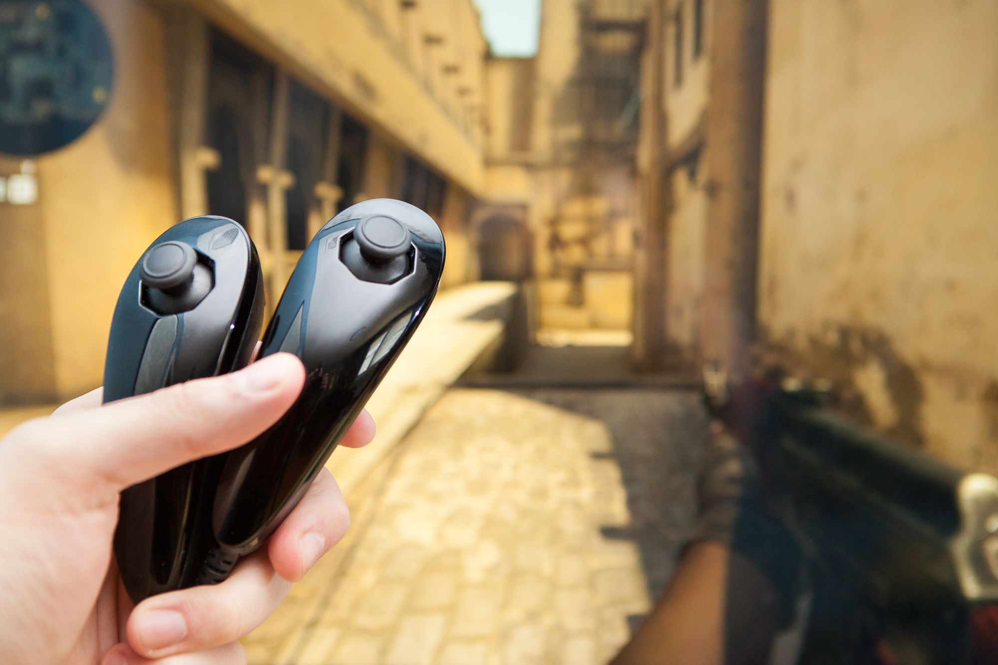
Playtime!
It’s time to put the the pedal to the metal plastic and see what this baby can do!
After thorough testing I’m happy to report that the controller works about as well as a typical controller in Forza. Inputs are responsive, smooth, and mapped intuitively. The standard throttle and steering controls in particular work perfectly, and really add to the RC car “feel”.
Although it’s a necessary evil, the different control “modes” definitely take a little while to get used to – particularly with the ‘alternate’ option switch on the grip. I’d often get distracted and open a menu or finish an event and forget which ‘mode’ I’m in, wondering why my inputs weren’t working right. Thankfully this happened less and less as I got used to which modes are required where. It’s helpful to keep a mental map of which controls are mapped where, and in which mode.
There are still times when a “standard” controller is superior, mostly when both the left and right thumbstick are required simultaneously (such as in photo mode). Though in all of my playtime I don’t think I ever encountered a moment where the RC controller wouldn’t work as a substitute, though it may sometimes be a poor one.
The one noticeable drawback is that the response time is longer than would be ideal. Because it’s reading the servo outputs from the receiver, updates run at 50 Hz (20 ms) with up to 2.2 ms of additional delay depending on the input state (pulse width). Unfortunately this can’t be improved without using a separate wireless system.
Wrapping Up
I’m thrilled with how this project turned out. With most projects there’s a list of lessons learned or things I would have done differently, but I’m happy to say that’s not so with this one. Just about everything went to plan, and the things that didn’t were due to issues in the execution (e.g. lifting a pad on the receiver) and not issues with the concept.
Simplify, then Add Controller
That being said, there were a few ideas I chose not to implement.
One of these was creating a modular ‘adapter’ for the receiver rather than making the dedicated USB dongle. This would let the user keep the receiver in its stock form for different projects and plug or unplug the XInput USB adapter as needed via the 6×3 pin headers. This had promise, but I eventually ditched the idea because it wouldn’t be as clean as a self-contained dongle and the connection depended heavily on the shape of the receiver (i.e. it would not be universal).
For the controller I could have also used either analog or multiplexed (resistor ladder) inputs on channels 3, 5, and 6. Although I eventually decided extra inputs weren’t needed due to the slide switch ‘modes’, it might have been nice to have a mini joystick up top in addition to the two buttons.
Downloads
As with most of my projects the hardware and software for this controller is fully open source, licensed under GPLv3. If you’d like to make this or something similar yourself, you can find everything including the PCBs, CAD files, and source code on GitHub.
Future Thoughts
Looking forward, this also opens the door for other RC-controlled projects using microcontrollers. The one at the forefront of my mind is a remote-controlled DeLorean – but that’s a long ways off in the future.
In the meanwhile, I’ll just have to be content with my (virtual) RC McClaren Senna.
Parts List
Here is a fairly exhaustive list of the parts used for this project. Note that many of these (and many above) are Amazon affiliate links, which help fund the content on this site. Thank you for your support!
RC Controller
Channel 3 PCB
Channel 5/6 PCB
- 2x C&K PTS645 SMD Tactile Switch (130 gf)
- 2x 10K Ohm Resistor, 0805 Package
- JST PH 4-Position Vertical Header
- 2x JST PH 4-Position Socket Housing
- 8x JST PH Crimp Sockets (24-28 AWG)
- 26 AWG Stranded Hook-Up Wire
- 3x M2-6 Thread-Cutting Screws
- Hatchbox 1.75 mm Black ABS Filament (for button caps)
Receiver
- SparkFun Pro Micro with USB-A Port
- 30 AWG Enameled Copper Wire
- Hatchbox 1.75 mm Black ABS Filament (for case)
- 3M Double-Sided Tape
- 0.030″ Polystyrene Sheet, White
- 1x M2-6 Thread-Cutting Screws