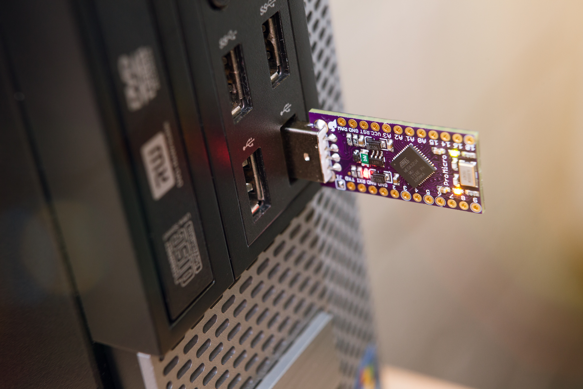
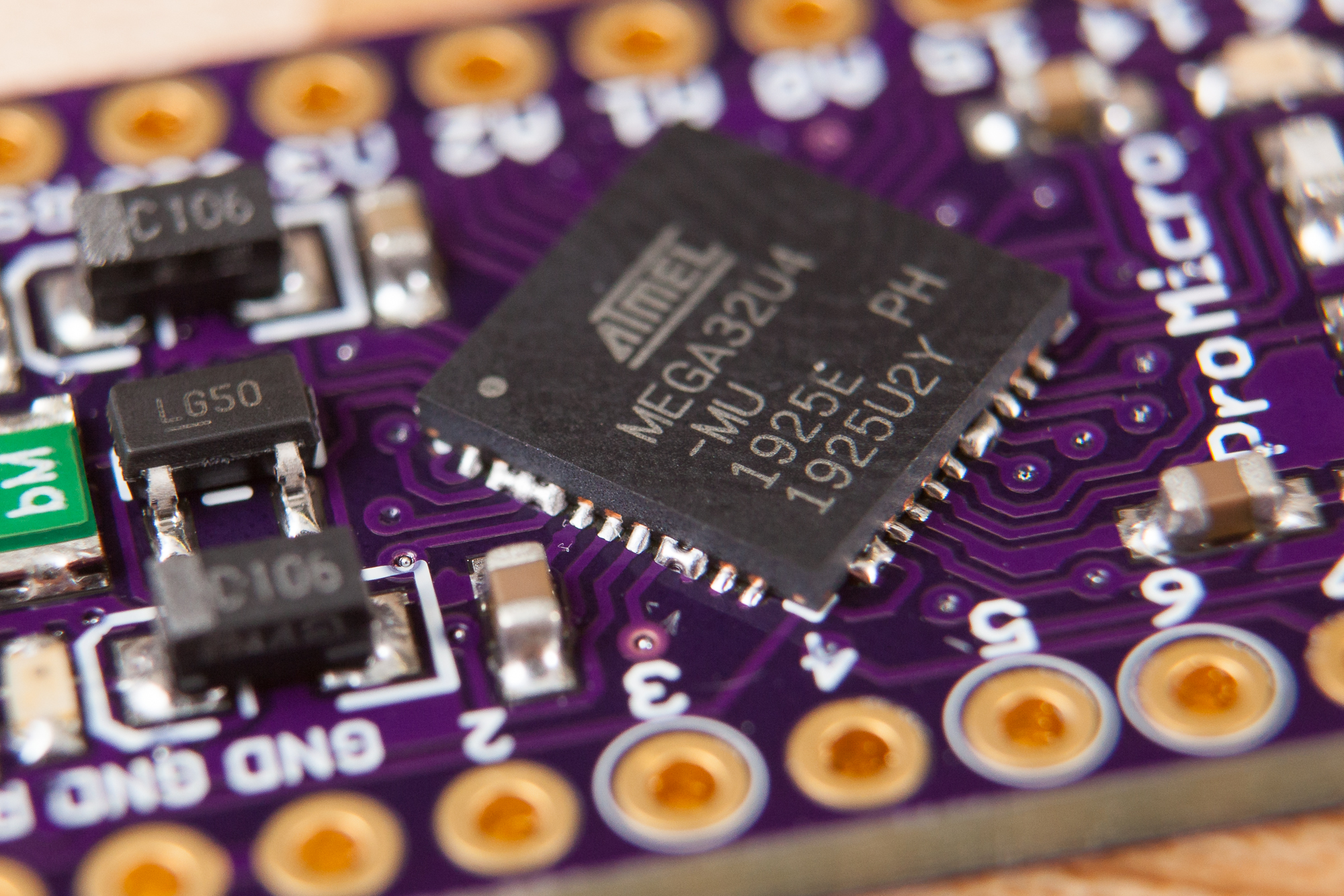
Lately I’ve been working on a project that will use an Arduino to translate signals from a wireless receiver into USB HID inputs for my computer. I had the perfect microcontroller picked out too: the SparkFun Pro Micro, which uses the Arduino-compatible ATmega32U4 and has enough I/O pins for my project and then some. There’s just one problem – the Pro Micro doesn’t have a USB-A port to plug directly into a computer! Instead it has a micro USB-B port, and requires a short cable to connect it to a PC.
Luckily for me the Pro Micro, like many of SparkFun’s designs, is open source and licensed under Creative Commons Share-alike. So I decided to dive in and modify the design to create my own version of the Pro Micro with a USB-A port!
Modifying the Board
The first step in building my own board is to modify the original design files, which were built using CadSoft EAGLE back in 2015 (before CadSoft was purchased by Autodesk). I already had EAGLE 7.7.0 installed for working with legacy projects, so I loaded up the Pro Micro project files and got to work.
Changing the USB Port
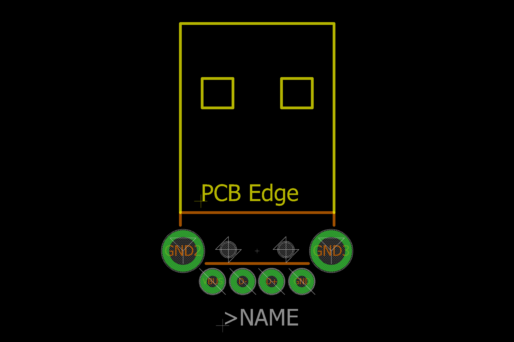 Before anything else, I needed the “package” (what EAGLE calls a footprint) for the USB-A connector that is replacing the micro USB port on the board. In EDA terminology, a footprint is the layout of the copper pads, mounting holes, and cutouts used to physically attach and wire the component to the circuit board. And because EAGLE has a tightly integrated project flow from schematic through to board layout, I also needed a schematic symbol to match.
Thankfully SparkFun came through once again, as their own EAGLE library is also open source (CC BY-SA 4.0) and they have an older release tagged for version 7.7.0. Within the SparkFun-Connectors library are a number of USB port “devices” (symbols with associated packages), including the “USB-A-H” device for a through-hole mounted USB-A port. Now to add it to the Pro Micro!
The Schematic
Because EAGLE tightly integrates the schematic and board layout together, the first step is actually to modify the schematic in order to remove items from the board. After right-clicking on the USB-B port (the symbol marked “USBAB”) in the schematic and selecting “Delete”, its footprint immediately disappears from the board layout as well.
Once I had imported and activated (what EAGLE calls “Using”) the SparkFun connectors library, I added the USB-A-H symbol and rearranged the net connections to match.
The Board Layout
With the schematic changed to use the new symbol it was time to integrate the USB-A port into the PCB. I positioned the footprint in the dead center of the PCB (X: 0.35″) and moved it as far down as I could until it was just barely clear of the silkscreen around the J1 jumper. After dragging the top board edge and polygon copper pours up to match the silkscreened “board edge” of the USB-A footprint it was time to connect the traces.
This ended up being more involved than I had hoped. My original goal was to keep things simple and change the Pro Micro board as little as possible, but because the pad connections on the USB-A footprint are in a different order than the USB-B footprint I had to make some more significant modifications.
For starters, I swapped the positions of the R5 and R7 resistors (the inline 22 Ω resistors for the USB data lines) to reduce the number of vias needed. I also repositioned the vias to the left of the “RAW” pin to provide clearance for the USB ground pad and the rerouted “RAW” and “RESET” traces.
Since I didn’t have SparkFun’s DRC ruleset for the Pro Micro (and I’m not using their fab anyways!) I decided just to “wing it” and just do my best to keep traces the same size and at a reasonable distance from each-other. Don’t follow my example…
Adding Silkscreens
At this point the board is functionally complete and ready to be sent off to the PCB fabricator! But before that I’m going to add a little style in the form of the Parts Not Included logo. I exported the board’s outline and pads from EAGLE to PDF, then imported them into Adobe Illustrator. I then laid out the logo and text, resized it to fit the board, and set about figuring out how to import the finished graphics into Illustrator.
Believe it or not this was the hardest part of the project. It turns out that it is not easy to get high quality vector graphics into EAGLE.
The solution that kept coming up again and again was to use an EAGLE script called “svg2poly” in combination with Inkscape to simplify the graphic shapes (flatten curves, split compound shapes, etc.). But no matter what I tried I just could not get EAGLE to cooperate – the script kept throwing errors and spitting out garbage data on even the simplest shapes.
The Parts Not Included logo for the Pro Micro, as previewed in svgtoeagle
What eventually worked for me was this awesome online converter called “svgtoeagle” by the incomparable Gordon Williams (of espruino fame). In Illustrator I converted the logo to use only line segments by adding extra anchor points and using the “Simplify” function to reduce all segments to straight lines (Object -> Path -> Simplify). Then I exported the logo as an SVG, imported it into the online converter, and in no time flat I had a perfect EAGLE compatible footprint containing the logo as a silkscreen.
With logo in hand, I created the corresponding schematic symbol and device in a new EAGLE library and then imported them into the Pro Micro project. After removing the large SparkFun logo (sorry!) and putting the Parts Not Included logo in its place, the board is now ready for fabrication.
Manufacturing
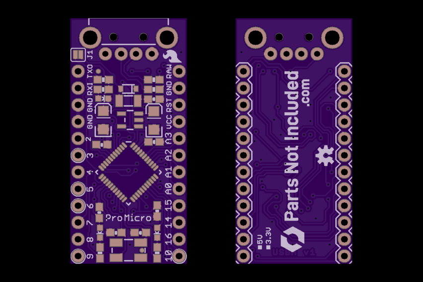
Pro Micro v1.0 PCB previews, as generated by OSH Park
The Pro Micro board is far too complicated for me to make at home, so instead I’m going to have a few boards manufactured by a proper PCB fabrication house.
Generating Gerbers
At the moment I only need a handful of these boards for a project, so I’m using OSH Park for fabrication due to their low prices for small boards and quick turnaround time. Because of that it makes sense to use OSH Park’s CAM workflow to generate the Gerber files needed for manufacturing. I downloaded the 2-layer CAM file from OSH Park’s GitHub (8e1522c circa 7.7.0) and loaded the job into EAGLE’s CAM Processor.
For the Pro Micro the CAM job needs two minor tweaks. On both the “Top Silkscreen” and “Bottom Silkscreen” sections, the silkscreen part reference layers need to be disabled. For the top silkscreen that’s layer #25 (“tNames”) and for the bottom silkscreen that’s layer #26 (“bNames”).
After processing the CAM job in EAGLE, I uploaded the gerber files to OSH Park’s website and ordered 3 boards using their standard purple solder mask and ENIG plating. The total came out to $5.20 including shipping, with roughly a two week turnaround time.
Solder Stencils
Since this is a reasonably complex SMD circuit board, I thought it might be fun to spend a little extra and try a proper steel solder stencil for this project. I’ve always either placed the solder paste by hand or used a DIY vinyl stencil, so this was going to be new for me.
OSH Park recommends OSH Stencils as a provider for low-cost solder stencils, priced by size. I created an account, uploaded the top solder paste gerber (tcream.ger), and noticed a problem. Because it’s a pad like any other, the voltage jumper in the corner of the board is marked as a solder paste area! Although I’m only making 5V versions at the moment, the 3.3V variants of the Pro Micro don’t use this jumper and the paste would need to be wiped off for each board.
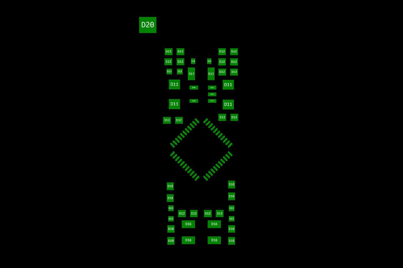
The Pro Micro “tCream” Gerber in KiCad’s GerbView. Note the large ‘D20’ pad in the top left for the voltage level jumper.
Rather than trying to modify the board in EAGLE to ignore solder paste for those pads, I took the easy way out and modified the Gerbers directly. Gerber files are just plain ASCII text files, more-or-less G-code designed around a photoplotter. Basic modifications like removing pads are straightforward.
Using KiCAD’s GerbView, I identified the voltage jumper as using code D20 with the pads underneath using code D19. Pads using those aperture settings are listed in the file under the D20* and D19* headings, respectively. These pads were easy to find at the very bottom of the paste Gerber and deleting them removed the voltage jumper from the layout. The Gerber was then ready to upload and process into a stencil.
I ordered the standard 4 mil stainless steel stencil, with the smallest border size I could get (0.75″) to cut down on cost. The stencil was engraved (for free!) with the project name, project version, and the date. With the cheapest shipping option, the total came to just under $14 USD.
Sourcing Parts
With the circuit boards and solder paste stencil ordered and underway, the next step is to find and order the components as-specified in the bill of materials (BOM).
I exported the auto-generated BOM from the EAGLE schematic and removed all of the extraneous parts like the silkscreen graphics and the fiducial markers, then combined like parts to form the initial list. After a few rounds around Mouser’s parametric search, here’s the final shopping list for the 5V boards:
| Type | References | Count | Value | Package | Description | Manufacturer | Part # |
|---|---|---|---|---|---|---|---|
| Capacitor | C1, C3 | 2 | 0.1uF | 0603-CAP | Capacitor | AVX | 0603YD105KAT2A |
| Capacitor | C2, C4 | 2 | 22pF | 0603-CAP | Capacitor | AVX | 06035A220JAT2A |
| Capacitor | C5, C6, C10 | 3 | 1uF | 0603-CAP | Capacitor | AVX | 0603YD105KAT2A |
| Capacitor | C13, C19 | 2 | 10uF | EIA3216 | Capacitor Polarized | AVX | F931C106KAA |
| Diode | D2 | 1 | - | SOD-323 | Diode | SMC Diode Solutions | 1N4148WSTR |
| LED | D1 | 1 | Yellow | LED-0603 | LEDs | Wurth Elektronik | 150060YS55040 |
| LED | D3 | 1 | Green | LED-0603 | LEDs | Wurth Elektronik | 150060VS55040 |
| LED | LED1 | 1 | Red | LED-0603 | LEDs | Wurth Elektronik | 150060RS55040 |
| MCU | U3 | 1 | ATMEGA32U4 | QFN-44 | Atmel 44-pin 8-bit Microcontroller | Microchip Technology | ATMEGA32U4-MU |
| Polyfuse | F1 | 1 | 500mA | PTC-1206 | Resettable Fuse PTC | Bel Fuse | 0ZCJ0050FF2G |
| Regulator | U2 | 1 | MIC5219 | SOT23-5 | Voltage Regulator LDO | Microchip Technology | MIC5219-5.0YM5-TR |
| Resistor | R2 | 1 | 10K | 0603-RES | Resistor | Yageo | RC0603FR-0710KL |
| Resistor | R4, R6 | 2 | 330 | 0603-RES | Resistor | Yageo | RC0603FR-07330RL |
| Resistor | R5, R7 | 2 | 22 | 0603-RES | Resistor | Yageo | RC0603FR-0722RL |
| Resistor | R11 | 1 | 1K | 0603-RES | Resistor | Yageo | RC0603FR-071KL |
| USB Port | J1 | 1 | USB-A-H | USB-A-H | USB Connectors | SparkFun | PRT-00437 |
| X-Tal | Y1 | 1 | 16MHz | CRYSTAL-SMD-5X3 | Crystal | IQD | LFXTAL056095Bulk |
Full disclosure: these are the parts that I ordered, and probably not the ideal parts for the board. If you’re going to build one of these yourself, I urge you to do your own research.
Sourcing most of these parts was straightforward. For any given component I tried to stay with the most widely available version of the part that fit the specs (value, footprint, type, etc.). I also did my best to use the same manufacturer for like components to keep things simple and make the board more uniform. That being said, there were a few parts that required a bit of research and guesswork to get right.
Unlike most of the other components on the board, the voltage regulator has a specified part number in EAGLE: “MIC5219”, which is a Microchip Technology LDO. On the schematic, the “Max Voltage Input” is listed as 16 VDC, although all of the the 5V versions of the MIC5219 I found are limited to 12 VDC max. I don’t know where this discrepancy is – perhaps the input voltage note in the schematic is incorrect, the version of the regulator they used 5 years ago is no longer manufactured, or maybe they used a different regulator altogether and forgot to update the part number. Regardless, I’m building these boards with USB-A specifically to connect and be powered by a PC, so having a 12V limit on the regulator is no big deal.
The SparkFun engineers who created the original schematic also specified a pair of 22 pF capacitors in parallel with the 16 MHz crystal oscillator. Assuming stray capacitance on the board is around 5 pF, this means the ideal oscillator should have a load capacitance of 16 pF – which matches the crystal I selected above. I found this article helpful for specifying the proper load capacitance.
Last but not least, I decided to use the “SparkFun” brand USB-A port, which is also sold through Mouser’s storefront. The datasheet on SparkFun’s website says the USB port is made by “4UCON”, but I’m sure other through-hole USB connectors will have similar footprints. Since SparkFun did nearly all of the heavy lifting to make the Pro Micro in the first place, I thought I would give a little bit back. Hats off to you guys!
All-in-all, ordering these parts for a 1-off board from Mouser will cost about $10 USD, not including shipping or tax. Those $3 knockoffs on AliExpress are looking pretty good right about now…
Assembly

Packages galore! The components from Mouser, the PCBs from OSH Park, and the stencil from OSH Stencils.
A few short weeks later and I had three new packages on my workbench! The PCBs from OSH Park, the stainless steel stencil from OSH Stencils, and all of the components from Mouser. Time to put everything together!
Fixing Mistakes
Trouble reared its ugly head as I was sanding the panelization sprues off of the PCBs. Once I had the front of the board cleaned up I was eager to try out the USB-A port and see it on the board for the first time!
Naturally, it didn’t fit.
I should have read the fine print in the SparkFun connector library, which says:
USB-A-H is throughly [sic] reviewed, but untested.
The edge of the circuit board extended just past the cutout opening on the USB port itself, preventing the port from sliding down and mating with the circuit board. It turns out that the silkscreen marker in the footprint for the top of the cutout was 0.1 mm higher than the datasheet says it should be (3 mm up from the origin instead of 2.9 mm), and the board edge I set was 0.05 mm past that already high marker. Oops.
After considering my options I decided to just sand off the edge a tiny bit until the port fit snugly. This was a little messy but ended up working just fine. Thankfully sanding the edge didn’t expose the ground pour enough to create a bridge between the USB shield ground and the signal ground.
Applying Paste
The stainless steel stencil from OSH Stencils came taped to a large piece of cardstock to keep it flat during shipping and was bundled with some stickers (swag!) and a credit card sized piece of plastic labeled “solder spreader”. After removing the stencil and inspecting it for damage, I set to applying the paste.
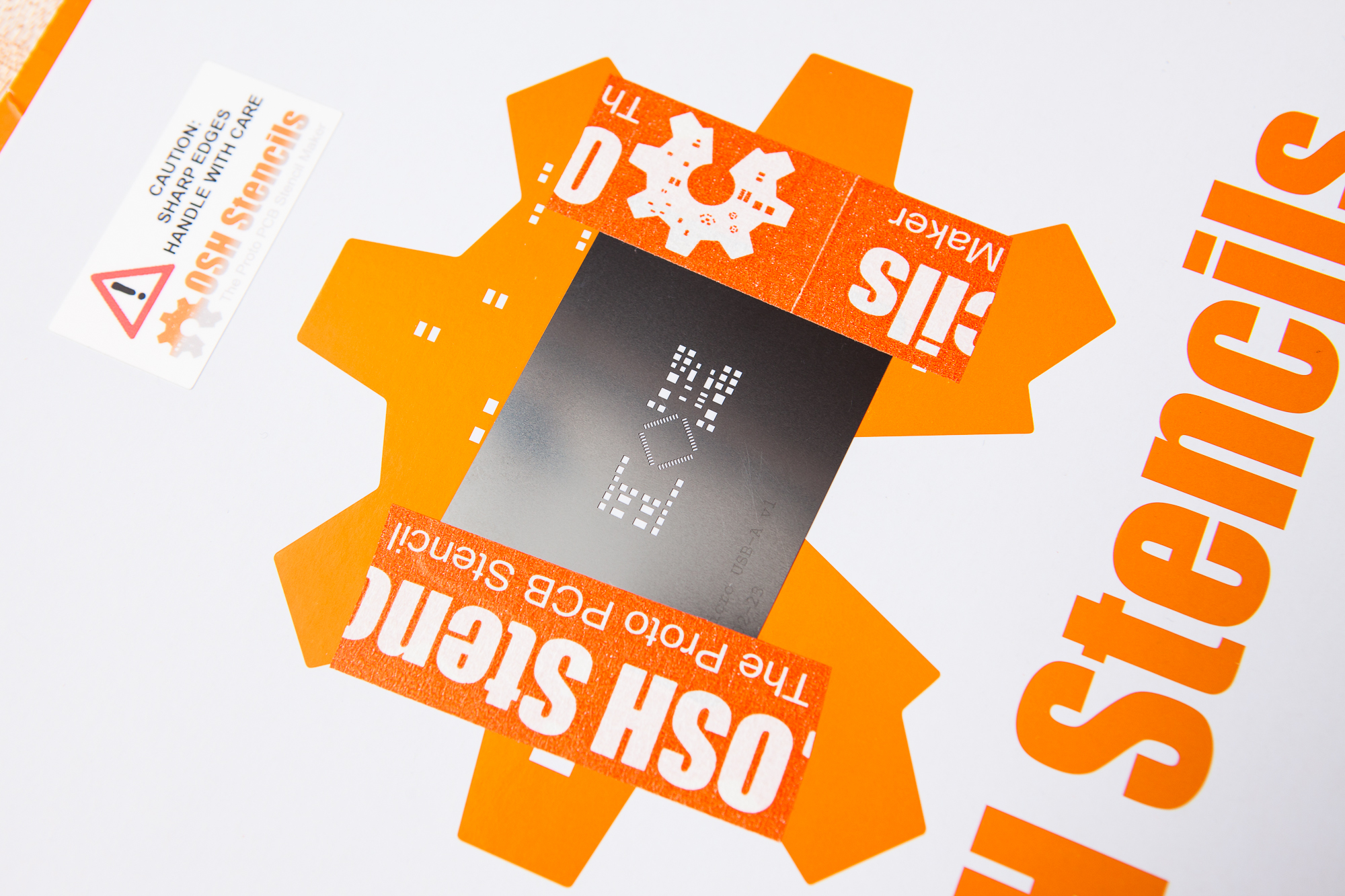
The Pro Micro stainless steel stencil, as shipped
I placed the sanded Pro Micro boards between a pair of 1.6 mm acrylic ‘L’ jigs and aligned the stencil until I could only see the ENIG coated pads through the opening. Then I taped down the stencil in place with a small piece of painter’s tape and applied a thick bead of “no clean” leaded solder paste at the top. One constant but firm stroke with the included “solder spreader” and the paste was applied and ready to go!
I know the steel stencil was overkill for this project, but it was quite well built and made it a piece of cake to cleanly apply just the right amount of paste to all of the pads. I’ll have to think about getting more “proper” solder stencils for future projects with complex PCBs.
Placing Components
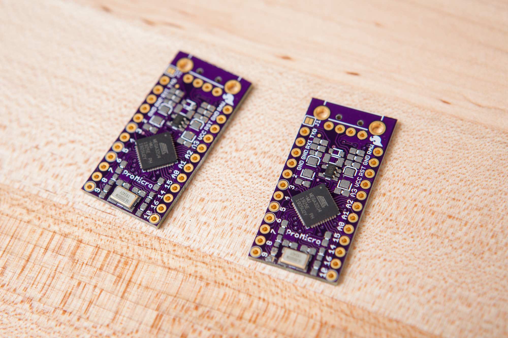
Placing components on the board. The crystal, microcontroller, and voltage regulator are in their final positions.
I’m not lucky enough to own my own pick and place machine, so I had to do things the old-fashioned way and place all of the components on the board using a pair of fine anti-static tweezers and a steady hand.
Making this process slightly more difficult, the component references on this board are a bit of a mess. It looks like the designers at SparkFun annotated the board once and then never updated it as they continued with the design. The board is missing several sequential references, including R1, U1, and C7 among others. The LEDs are split between using the “LED” and the “D” designator, and there’s often little rhyme or reason to how references are grouped.
So to help with this I exported the board outline, top solder paste, and top silkscreen from EAGLE into Illustrator. After blowing up the board to fit a letter-sized sheet of paper, I then added the references next to the components along with some additional indicators for the polarized parts. I printed this out and kept it on the workbench while I was laying out parts, which was a huge help.
When I ordered the components from Mouser I also put the board references as a “Customer #”, so the references for each component were printed on the outside of each bag. This made it easy to find components for each reference during assembly without having to refer to the bill of materials.
For placing components I worked inside to out, starting with the most complicated footprints in the center (the 32U4, regulator, crystal) and moving to the simpler ones around the perimeter. All-in-all it took about 40 minutes per board to get all of the parts situated. Time for reflow!
Soldering! And Re-Soldering
My original plan for reflowing the paste was to use an old toaster oven I have, but after a few tests I determined that it wasn’t powerful enough to get up to the temperatures needed. So instead I decided to solder the whole board using my hot air rework station. This takes a little longer and you can only do one board at a time, but it works just as well.
The first two boards were looking pretty good until I took out a loupe and inspected more closely: the pins on the 32U4 microcontrollers were bridged!
Solder bridges between the microcontroller pins, caused by repositioning the microcontroller before reflow.
I tried to fix the pads with my soldering iron, but the tip wasn’t small enough to make contact between the pads on the board and the small visible pads on the sides of the microcontroller. Because I didn’t have any flux handy (a big mistake in hindsight), I tried applying some extra rosin-core solder and then wicking it off. Repeated failed attempts at this only ended up burning the microcontroller and rubbing off some of the solder mask on the PCB.
After ordering a tin of flux and taking a few days to rethink the problem, I decided to use my hot air rework station to remove the microcontroller altogether and resolder it. Once the microcontroller was free I slathered the pads in flux and added a small bead of solder to my iron, then tried to drag solder across the pads until they were properly “domed” without bridging to the next pad. The excess solder collected between the final two pads in the row and was cleaned up with some copper wick. I repeated this process for each row in turn before finally using some cotton swabs and isopropyl alcohol to remove the flux residue.
With the pads properly tinned, I carefully replaced the microcontroller and used my hot air station to reflow everything. I was probably a bit aggressive in reheating the solder since it was next to impossible to judge whether it had properly reflowed, but the microcontrollers seem to be holding up well so far.
When I first placed the microcontrollers on the paste I had wiggled them around a little bit on the board so they were properly aligned. I’m guessing that this “wiggling” also spread the paste around, causing the solder to bridge the pads. When I placed components on the third board I trusted the solder to self-align the microcontroller if I got it “close enough”, and had no issues with bridging on that board.
After all of the SMD parts were properly reflowed, I took out the through-hole USB-A ports and soldered them on by hand. I also bridged the “J1” jumper, as the boards I made are all configured for 5V.
Flashing and Fuses
The final step before these boards are “production ready” is to burn the fuses on the microcontrollers and then flash the Arduino bootloader.
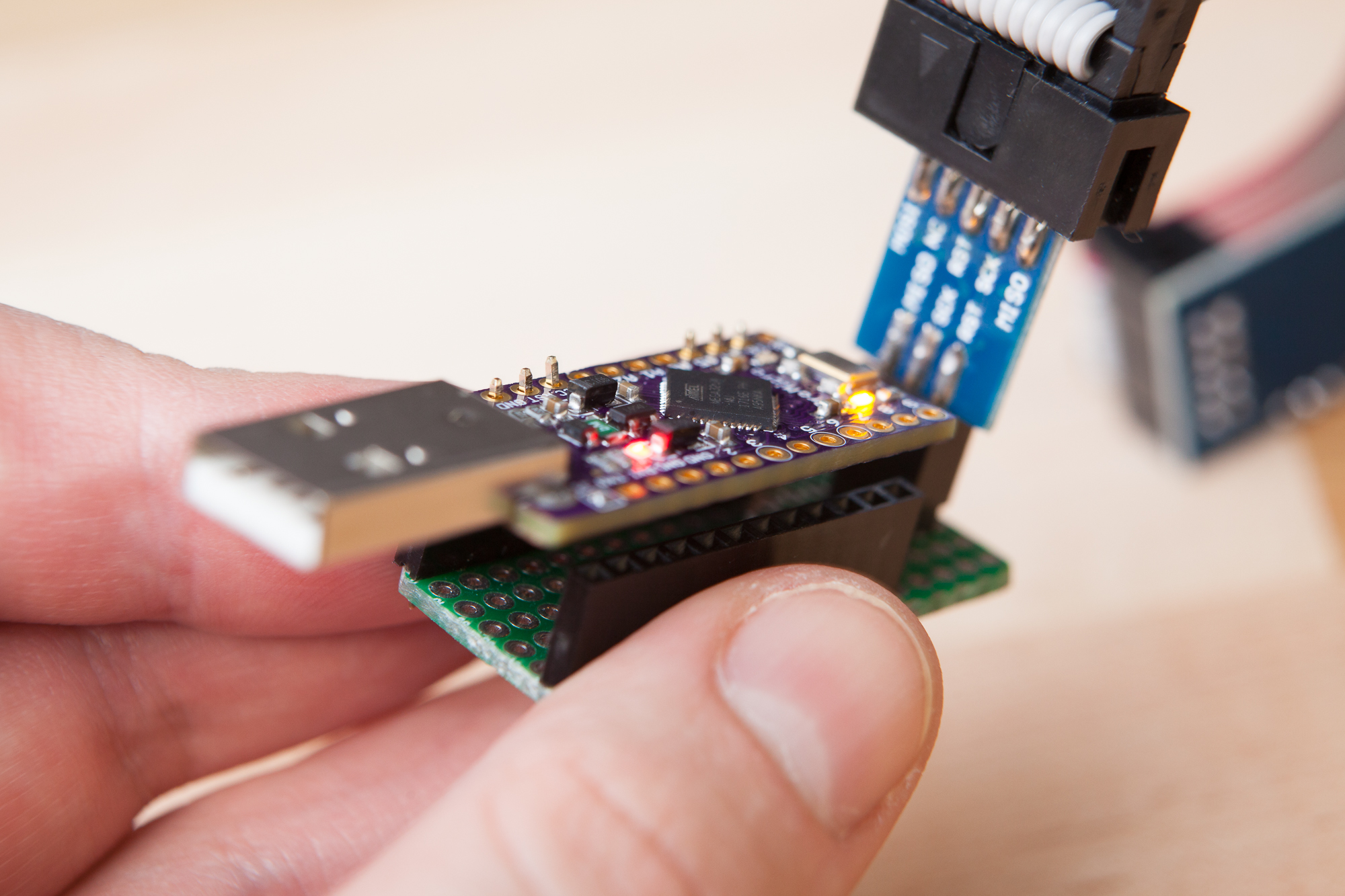
Since the Pro Micro doesn’t have the standard 3×2 SPI programming header, I built my own programming adapter using a piece of perf board and some jumper wires. To avoid soldering to the Pro Micro headers prematurely I bent some 0.1″ pin headers to make my own DIY pogo pins. Then with the USBasp programmer connected it was time to flash the boards!
Burning Fuses
From the factory, the ATmega32U4 chips are programmed with the following fuse settings:
Extended: 0xF3
High: 0x99
Low: 0x5E
The 5V SparkFun Pro Micro boards, on the other hand, use these fuse settings:
Extended: 0xCB
High: 0xD8
Low: 0xFF
These “fuse” bits are low level settings, separate from the non-volatile flash memory, that change how the microcontroller behaves. The fuses can be burnt from the command line using avrdude:
avrdude -c usbasp -p m32u4 -v -e -U efuse:w:0xcb:m -U hfuse:w:0xd8:m -U lfuse:w:0xff:m
Note that the -e flag is needed to erase the flash from the factory in order to clear the lock bits and make the fuses writable.
Next let’s do a rundown of the changes made by these fuse settings. All quotes and page numbers are references to the ATmega32U4 datasheet.
Use External Clock
From the factory the 32U4 is configured to use an 8-16 MHz low power crystal oscillator with a clock prescaler of 8, resulting in a 2.0 MHz clock speed with the 16 MHz crystal (page 29). The 5V SparkFun Pro Micros use an external 16 MHz crystal oscillator, and the fuse settings need to be modified to utilize it at full speed.
First the clock prescaler is disabled by unprogramming (setting to ‘1’) bit 7 of the low byte, CKDIV8. Next bits 3:1 of the low byte (CKSEL3..1) are set to ‘1’ to use a crystal oscillator with a frequency range between 8.0 – 16.0 MHz (page 30). Last but not least, CKSEL0 along with SUT1 and SUT0 (bits 0, 5, and 4 of the low fuse byte respectively) are all set to ‘1’ to indicate a crystal oscillator with “slowly rising power” (see table 6-4 on page 31).
Bootloader Enable
The SparkFun fuse settings make two changes that enable the use of the Arduino’s USB bootloader.
First, bit 0 of the high fuse byte, BOOTRST (“Boot Reset”), is programmed (set to ‘0’). This causes the microcontroller’s reset vector to point to “the boot flash start address” after a reset (page 340). In plain English, it causes the microcontroller to start running the bootloader after it’s reset instead of running the application code.
Second, bit 3 of the extended fuse byte, HWBE (“Hardware Boot Enable”), is unprogrammed (set to ‘1’). If this is enabled, the microcontroller will use the state of the HWB pin to check if it should reset to the application or to the bootloader:
When the HWBE fuse is enable the ALE/HWB pin is configured as input during reset and sampled during reset rising edge. When ALE/HWB pin is ‘0’ during reset rising edge, the reset vector will be set as the Boot Loader Reset address and the Boot Loader will be executed
This setting is overridden by the BOOTRST fuse, making this option redundant and it is thus disabled. See figure 27-3 on page 341.
It’s worth nothing that the HWB pin is not used for other purposes on the Pro Micro, and is simply tied to ground. Whether the HWBE setting is enabled or not the microcontroller will still jump to the bootloader on reset.
Disable JTAG
Bit 6 of the high fuse byte, JTAGEN (“JTAG Enable”), is unprogrammed (set to ‘1’) with the SparkFun settings. This disables the use of the JTAG interface on the board used for programming and debugging (pages 323-324).
The pins used for the JTAG interface are connected to Port F, which is also connected to the internal ADC and used for the “A0-A5” pins on the Pro Micro. Leaving this fuse enabled will prevent using those pins for general purpose I/O, which is why it is disabled.
Staying the Same
Those are all of the settings that changed in the fuses, but there are a number of settings that stayed the same as the factory defaults:
- Brown-out detection is enabled at VCC = 2.6 (
BODLEVEL= 011) - Serial programming and debugging is enabled (
SPIEN= 0) - Maximum bootloader size (
BOOTSZ= 00, 2048 words)
The fuse also changes bits 4 and 5 of the extended fuse, although I’m not sure to what end since these don’t have associated functions in the datasheet. It looks like that may be a bug with how avrdude reads and writes the fuses with specific programmers, but I don’t know for sure.
Flashing the Bootloader
Of course, burning the fuses only sets the board’s hardware into a working configuration. In order to get the Pro Micro running as a “real” Arduino, the final step is to burn a bootloader so that it can be reflashed over its USB port from the Arduino IDE.
The Pro Micro uses a variation of the Caterina bootloader with the hex file available for download from the SparkFun boards repository (raw). The hex file can then be flashed over the SPI interface using avrdude:
avrdude -c usbasp -p m32u4 -v -e -U flash:w:Caterina-promicro16.hex:i -U lock:w:0x2F:m
This command also contains an instruction to set the “lock” bits to 0x2F. This prevents the flash memory from being able to overwrite the bootloader without the use of an external programmer.
Both the fuse settings and the bootloader flash can also be done “automagically” using the Tools -> Burn Bootloader option in the Arduino IDE with the SparkFun AVR boards installed. But for this project I wanted to know exactly what was being written to the microcontroller, so I wrote and sent the avrdude commands myself.
Testing and Final Thoughts
The Pro Micros are done! They’re assembled, soldered, flashed, and fully functional. I was able to reprogram all three boards from their USB ports, and did a quick test with a blinking LED to check that every I/O pin was working properly. For good measure I also reprogrammed each board with an XInput “blink” sketch to test their USB capabilities. So far so good!
It looks like I have three new microcontrollers to play with. Now let’s sit back, crack open a cold one, and take one final look at this project in retrospect.
Cost Breakdown
This is a recurring theme on this site, but this was definitely not the most economical way to get a Pro Micro-esque board with a USB-A port.
- Boards (3): $5.20, shipping included
- Components: $10.04, $7.99 shipping + tax
Not accounting for consumables and labor, for one finished board with two extra PCBs it’s $23.23 plus tax. For three finished boards it’s $14.44 plus tax each.
These three boards I built were a little more expensive. For this project I purchased an optional (but incredibly useful!) stainless steel solder stencil ($13.63), a new tin of flux ($9.53, consumable), and a fresh syringe of solder paste ($17.50, consumable). I also purchased a few spare components as backups and to secure price breaks ($5.20). In total, each of these three boards cost me about $29.72 excluding labor. For comparison, a knockoff Pro Micro from Amazon (sans USB-A) is around $10 and around $3 from AliExpress.
Alternatives
Which brings us to alternatives. Building this customized microcontroller was not my first choice, but I do think in the end it will end up being the right choice.
The most obvious alternative is to use a different microcontroller board altogether. Of these the most promising were various “Beetle” boards that also have a 32U4 onboard but use a PCB-edge connector in place of the proper metal USB port. I’m not a big fan of using edge connectors as replacements for proper connectors because they tend to be unreliable at best and damage the mating connector at worst. These “Beetle” boards also expose fewer pins than the Pro Micro, and are missing one I absolutely needed for my project (pin 7, i.e. PE6).
Another option would have been to take an existing Pro Micro (or equivalent) with it’s micro USB port, and then create an add-on board that converts that existing micro port to USB-A. This is more-or-less what Shawn Hymel did when he built a “mouse jiggler” for SparkFun using a Pro Micro. It works, but the resulting assembly is larger, uglier, and more vulnerable to connection issues than having the USB port properly integrated into the rest of the PCB.
Moving Forward
The Pro Micro USB-A boards I assembled were version 1.0 (85c5db), and do not provide proper clearance for the USB port from the board edge (which needed to be sanded down). I’ve already pushed a few changes to the git repository to improve the board further, including:
- Fixing the board edge clearance (16cf9cc)
- Adding silkscreen labels for the USB pads (cb3fd71, modified by 2966911)
- Allowing more trace clearance around the USB vias (75495c2)
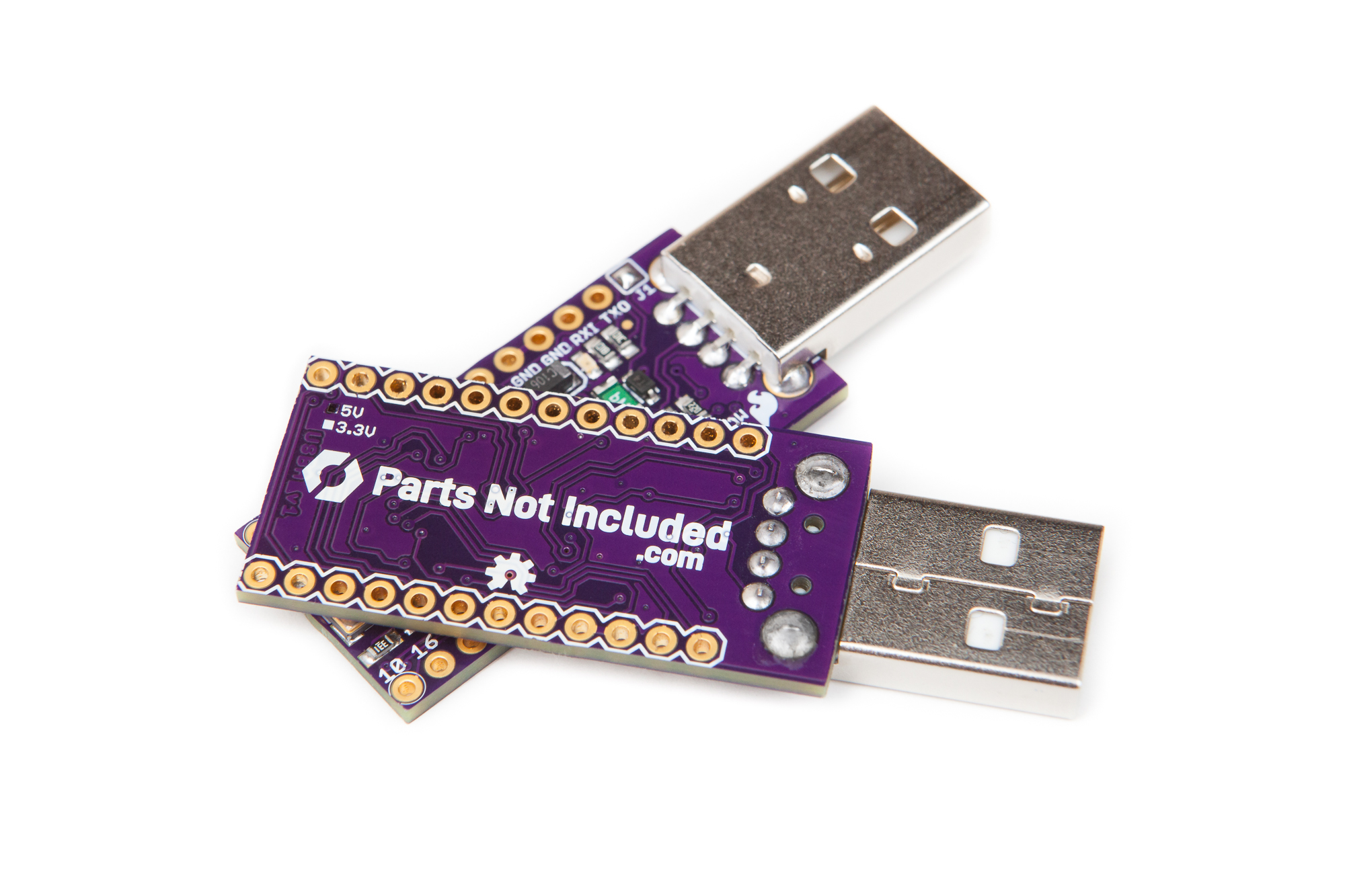
With these tweaks I’ve published a new version, “1.1“, and included Gerbers for anyone who wants to build their own copy of this board. Eventually it might also be wise to swap out the through-hole USB-A port for an SMD variant, but that’s a project for another day. You can download the board files and Gerbers from the GitHub repository.
All-in-all, I think this is a great alternative to the Micro-B version for those small projects that always need a PC connection and a variety of external I/O pins. If nothing else it’s a familiar package that can be used for all sorts of standalone USB projects.
I have big plans for the three microcontrollers I built. At least one of them will be the cornerstone of an upcoming controller project, with the others primed and ready to take the mantle for other USB creations. But even if the spares end up sitting in a drawer for the foreseeable future, I’m glad to have been the one to finally make the USB-A version of the Pro Micro a reality.
See you in the next one, and stay safe out there!
This post contains Amazon affiliate links. As an Amazon Associate I earn from qualifying purchases.