I’ve been doing a little streaming on Twitch, and a lot of streamers I follow have something called an Elgato Stream Deck. The Stream Deck is a small device with 15 buttons, each of which has its own customizable RGB icon. By configuring the bundled software, users can set button icons and macros to control your casting software, send messages in the stream chat, launch programs, and much much more.
Unfortunately the Stream Deck is out of my price range, at a whopping $149.99 retail. Fortunately I think I can make something that replicates the basic functionality for a fraction of that price: what I’m calling a “Stream Cheap”.
Although I’m focusing on using this as a replacement for a Stream Deck, at heart this is really a custom macro keyboard. It could be used as a hotkey board for any program. I’m just using it for OBS and Twitch.
Simplifying
The Stream Deck itself is a fantastic piece of tech. Adafruit did an interesting breakdown on stream, but it’s essentially a mini computer using an Atmel ARM926EJ-S driving a 480×272 resolution LCD. The buttons on top allow the LCD to shine through for the backlight icons, and push down on a touch matrix to trigger button presses.
There was a lot of engineering that went into making the Stream Deck, and I’m going to have to simplify. The #1 rule for this is cheap. I wanted to make something that people could reasonably build at home, at a much lower cost than an off-the-shelf Stream Deck. The fancy ARM processor is going to be replaced with a dirt-cheap AVR, the touch-matrix keys are going to be replaced by basic mechanical switches, and the customizable RGB icons are going to be swapped out for relegendable keycaps.
That’s just the hardware. When I say “basic” functionality, I do mean basic. Much of the power of the Stream Deck is in the bundled software, and I’m not going to spend the time to develop a complete software package to replicate everything. Fortunately though, I can replace the fancy USB communication with hotkeys from an off-the-shelf keyboard library and an Arduino. This is perfect, since most of what I need this device to control is OBS, which already has a great built-in hotkey manager.
Making the Stream Cheap
The obvious tool of choice for building this was a 3D printer: fast, cheap, and with minimal design constraints. This meant that I had a lot of freedom for designing the case so long as I avoided overhangs.
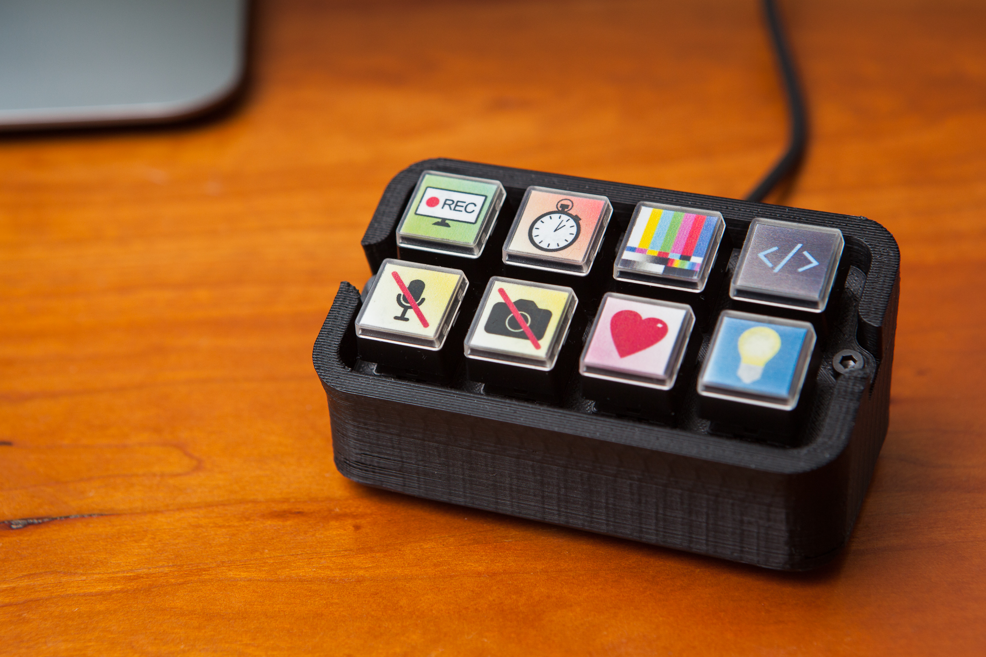
I chose a two-row design, each with four buttons for a total of eight hotkeys. Eight switches seems like just enough to accomplish what I need it to without getting exorbitant. It also keeps the footprint small on my desk.
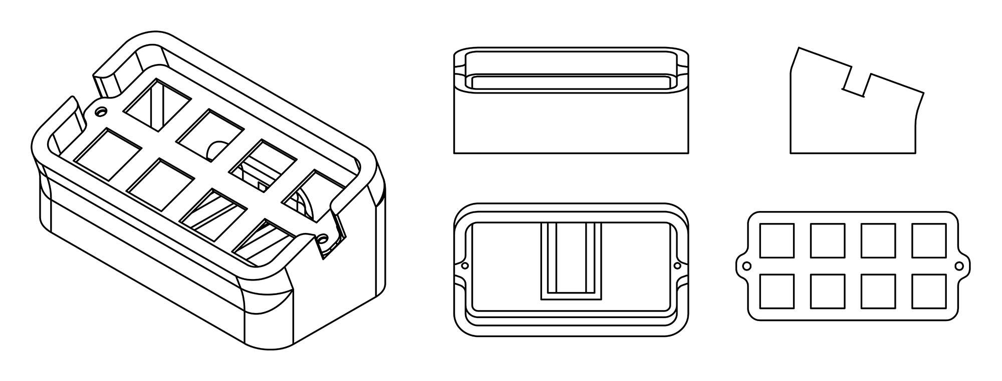
The final design is in two parts with a base and a faceplate. The base is a rounded rectangle that curves up to angle the buttons at 20° for easier viewing. It also accommodates the microcontroller with enough room for the backs of the switches and the requisite wiring.
The faceplate is a flat piece of 0.050″ plastic. Although I ended up 3D printing this for convenience, it could just as easily be laser-cut for a nicer finish.
Switchboard Assembly
After printing both parts of the case out of black ABS, it was time to assemble. I’m using Cherry MX Black switches, which are standard fare for mechanical keyboards and have plenty of keycap options. I picked up 8 from DigiKey for $6.32. These are a press-fit into the faceplate, and are retained with tabs.
With the switches in place I got to soldering. Although keyboards usually use a matrix to keep the number of wires down, I decided that with the limited number of switches I could get away with dedicating wires to each button. This also keeps the complexity down as I don’t have to worry about purchasing and installing diodes for each switch. Each switch got a separate signal wire, with the commons all being connected to a ground line. With eight switches, this makes 9 total wires. (I used 22 AWG wire for this. I could have used a smaller gauge to make packaging easier, but I didn’t have any on hand.)
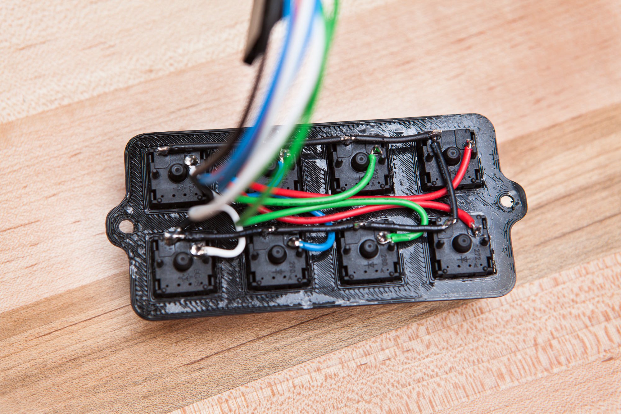
These wires all run to a female DuPont connector, which connects to a right-angle header on the Arduino Pro Micro acting as the brains of the operation. Using a header here allows me to pull out the switchboard or swap out the microcontroller as-needed. I’m using the DuPont connectors because they’re on-hand and easy to find, although it would have been wiser to use a polarized, positive-locking connector.
Update 2020-09-12: I keep getting comments that the wiring is confusing. I didn’t include a wiring diagram or a longer explanation than the one above because quite frankly the setup could not be any simpler. Each switch has two pins; it doesn’t matter which is which. One pin is a signal and connects to any I/O pin on the Arduino (I used pins 2-9). The other pin connects to ground (GND). Since ‘ground’ is the same for all of the switches, all of the ground connections were wired together and then connected to one pin on the Arduino (8 signal + 1 ground = 9 wires total). No diodes, no resistors, no matrix, no fuss.
Micro and Packaging
The microcontroller I’m using for this is a 5V Arduino Pro Micro, which is based around the Atmel 32U4 chip. The 32U4 supports native USB, which allows the Arduino to imitate an HID keyboard. It’s also small and very inexpensive.
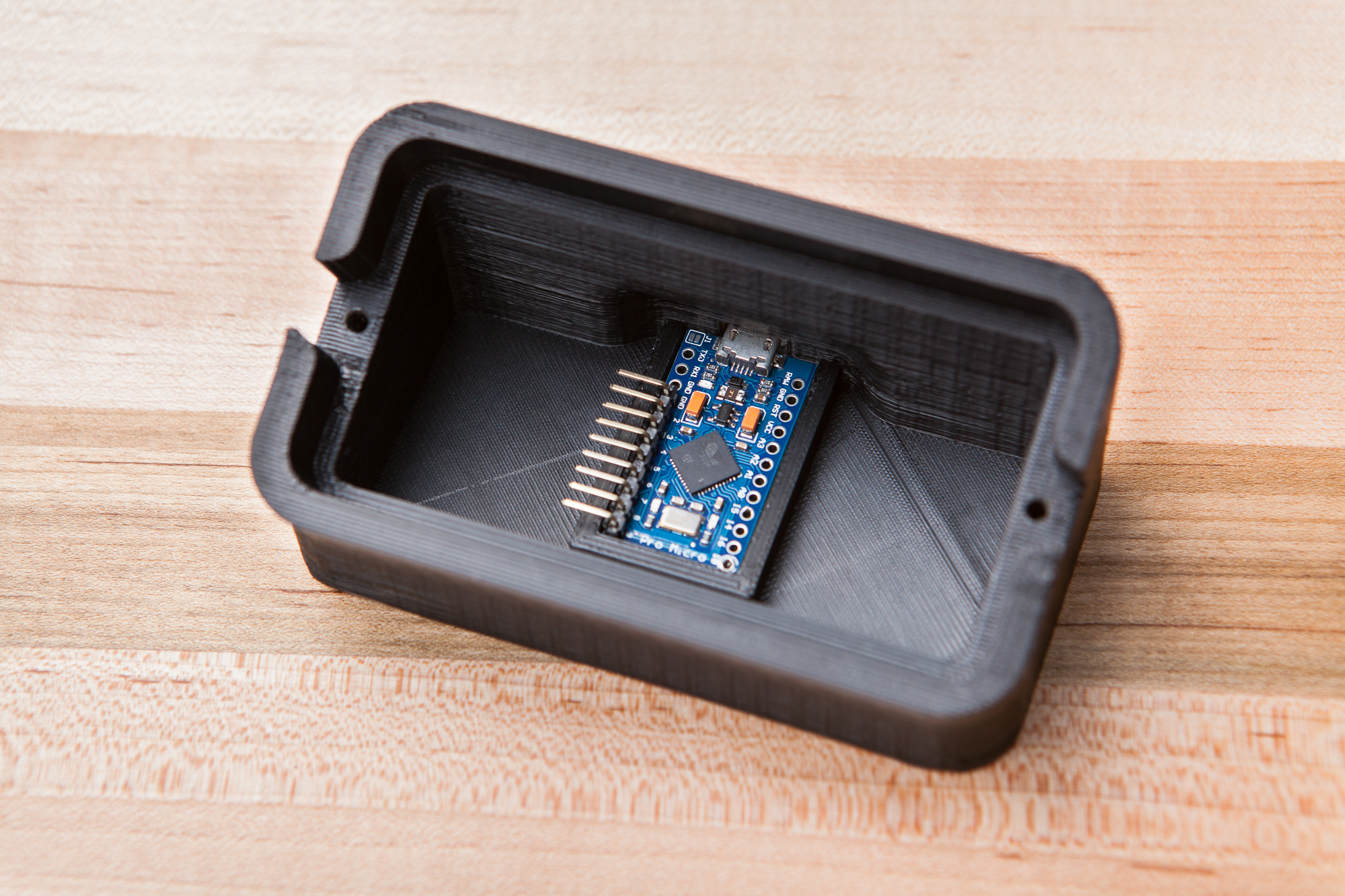
The footprint for the Arduino in the case has cutouts for the underside pins, and a cutout in the back for the USB port. Otherwise the walls around its perimeter should prevent it from sliding around, and support it during USB connects / disconnects.
After testing the switch and Arduino setup, it was time to stuff everything into the case. The two holes on the side of the case were tapped with an M3 tap, and then the Arduino was taped into its mounting position. The switchboard was connected and then the faceplate was attached using two M3 screws.
Keycap Icons
The last step to finish off the hardware was adding keycaps with custom images. I could just as well use regular run-of-the-mill keycaps with stock lettering or images, but where is the fun in that?
In anticipation of building this way-back-when, I purchased 20 re-legendable keycaps from MassDrop last year at about $1.40 each. These are the Rolls-Royce of re-legendable keycaps (har), but I really liked the styling. Although these are hard to find and pricey, you can find cheaper relegendable keycaps at places like Amazon or B&H.
The inside of each keycap is approximately 0.55 x 0.55″. I created an Illustrator template and set to work. This is what I came up with:
![]()
They’re a little campy, but they’re colorful and they’ll do the job. I printed these out on glossy photo paper using my home inkjet printer and cut them to size.
Stream Cheap Software
The last step is to make the software for the board. This is going to be relatively simple, as I can rely heavily on a pre-existing Keyboard library.
Secret Keys
When I set everything up to start streaming, I set a few hotkeys to do things like mute my microphone or switch scenes. Unfortunately it can be difficult to find an unused key to use as a hotkey, even on a full-sized keyboard. Often times I would accidentally tap a hotkey (e.g. numpad ‘-‘) while typing something, and have to be told by a viewer that my microphone was muted.
To avoid this problem for the Stream Cheap, I’m going to rely on some “secret” keyboard keys. Included in the HID keyboard spec are twelve additional keys: F13 through F24. These function keys are available to be ‘pressed’ by the USB spec, but aren’t physically on the keyboard. Even though the user cannot accidentally press them, in all other ways they act exactly like every other key.
These keys are picked up by hotkey-enabled programs, but otherwise won’t affect the computer’s functionality. This makes them perfect for a macro board.
Arduino Code
As of this writing, the official Arduino keyboard library does support keys F13 – F24, but this update was done recently and it has not been included in the most recent IDE release. I downloaded the updated library from GitHub and included it in the sketch folder to get access to these keys.
As of May 9th, 2018 version 1.0.2 of the Arduino Keyboard library was released and adds support for keys F13 – F24! You can update your library version in the libraries manager of the Arduino IDE.
The rest of the sketch is very simple: it polls each switch to check if the button has been pressed, and if so sends the respective key stoke to the PC. I’m also using a small helper class to poll each pin and handle press/release functions and debouncing.
As with all smartly-written programs that spam keyboard inputs, there is a failsafe if there is a hardware issue or an error was made during programming. On startup a safety catch will check if pin #1 (arbitrary) has been grounded, which will halt any further action.
/*
 *  Project     'Stream Cheap' Mini Macro Keyboard
 *  @author     David Madison
 *  @link       partsnotincluded.com/electronics/diy-stream-deck-mini-macro-keyboard
 *  @license    MIT - Copyright (c) 2018 David Madison
 *
 * Permission is hereby granted, free of charge, to any person obtaining a copy
 * of this software and associated documentation files (the "Software"), to deal
 * in the Software without restriction, including without limitation the rights
 * to use, copy, modify, merge, publish, distribute, sublicense, and/or sell
 * copies of the Software, and to permit persons to whom the Software is
 * furnished to do so, subject to the following conditions:
 *
 * The above copyright notice and this permission notice shall be included in
 * all copies or substantial portions of the Software.
 *
 * THE SOFTWARE IS PROVIDED "AS IS", WITHOUT WARRANTY OF ANY KIND, EXPRESS OR
 * IMPLIED, INCLUDING BUT NOT LIMITED TO THE WARRANTIES OF MERCHANTABILITY,
 * FITNESS FOR A PARTICULAR PURPOSE AND NONINFRINGEMENT. IN NO EVENT SHALL THE
 * AUTHORS OR COPYRIGHT HOLDERS BE LIABLE FOR ANY CLAIM, DAMAGES OR OTHER
 * LIABILITY, WHETHER IN AN ACTION OF CONTRACT, TORT OR OTHERWISE, ARISING FROM,
 * OUT OF OR IN CONNECTION WITH THE SOFTWARE OR THE USE OR OTHER DEALINGS IN
 * THE SOFTWARE.
 *
 */

// ---------------------------------
// Key definitions
#define BUTTON_KEY1 KEY_F13
#define BUTTON_KEY2 KEY_F14
#define BUTTON_KEY3 KEY_F15
#define BUTTON_KEY4 KEY_F16
#define BUTTON_KEY5 KEY_F17
#define BUTTON_KEY6 KEY_F18
#define BUTTON_KEY7 KEY_F19
#define BUTTON_KEY8 KEY_F20

// Pin definitions
#define BUTTON_PIN1 2
#define BUTTON_PIN2 3
#define BUTTON_PIN3 4
#define BUTTON_PIN4 5
#define BUTTON_PIN5 6
#define BUTTON_PIN6 7
#define BUTTON_PIN7 8
#define BUTTON_PIN8 9
// ---------------------------------

#include "Keyboard.h"

// Button helper class for handling press/release and debouncing
class button {
  public:
  const char key;
  const uint8_t pin;

  button(uint8_t k, uint8_t p) : key(k), pin(p){}

  void press(boolean state){
    if(state == pressed || (millis() - lastPressed  <= debounceTime)){
      return; // Nothing to see here, folks
    }

    lastPressed = millis();

    state ? Keyboard.press(key) : Keyboard.release(key);
    pressed = state;
  }

  void update(){
    press(!digitalRead(pin));
  }

  private:
  const unsigned long debounceTime = 30;
  unsigned long lastPressed = 0;
  boolean pressed = 0;
} ;

// Button objects, organized in array
button buttons[] = {
  {BUTTON_KEY1, BUTTON_PIN1},
  {BUTTON_KEY2, BUTTON_PIN2},
  {BUTTON_KEY3, BUTTON_PIN3},
  {BUTTON_KEY4, BUTTON_PIN4},
  {BUTTON_KEY5, BUTTON_PIN5},
  {BUTTON_KEY6, BUTTON_PIN6},
  {BUTTON_KEY7, BUTTON_PIN7},
  {BUTTON_KEY8, BUTTON_PIN8},
};

const uint8_t NumButtons = sizeof(buttons) / sizeof(button);
const uint8_t ledPin = 17;

void setup() {
  // Safety check. Ground pin #1 (RX) to cancel keyboard inputs.
  pinMode(1, INPUT_PULLUP);
  if(!digitalRead(1)){
    failsafe();
  }

  // Set LEDs Off. Active low.
  pinMode(ledPin, OUTPUT);
  digitalWrite(ledPin, HIGH);
  TXLED0;

  for(int i = 0; i < NumButtons; i++){
    pinMode(buttons[i].pin, INPUT_PULLUP);
  }
}

void loop() {
  for(int i = 0; i < NumButtons; i++){
    buttons[i].update();
  }
}

void failsafe(){
  for(;;){} // Just going to hang out here for awhile :D
}
With this uploaded, I went into OBS and tried setting a few hotkeys. IT WORKS!
Hotkey Assignments
This will probably change in the future, but here’s how I have the hotkeys set up. The key numbering goes from left to right, top to bottom:
- OBS Scene: Main
- OBS Scene: Be Right Back
- OBS Scene: Technical Difficulties
- (Custom button for stream integrations)
- OBS Source: Mute microphone
- OBS Source: Hide camera
- Twitch Chat: Spam “<3”
- Twitch Chat: Spam “💡” (Unicode 1F4A1)
The Twitch chat macros uses an OBS script I wrote, which stops and starts with OBS and hooks into its hotkey menu as well. The custom button (code symbol) is the odd man out – this is going to be a custom button that changes based on whatever interactive stream thing I use that day.
Conclusion
And it’s built! Total cost was around $20, although only because I splurged on the expensive keycaps and the nice switches. You could definitely build this for less.
As I stressed in the introduction, this device is not just limited to streaming! Because it works as a generic keyboard device, it can be used as a macro box for all sorts of programs! I could set simple shortcuts in any program, or use something like AutoHotkey for more complex commands without having to reupload the firmware.
All around this project was a huge success: the “StreamCheap” works exactly as I designed, taking the role of a Stream Deck at nearly a tenth of the cost!
If you’d like to build your own, you can download the 3D files from Thingiverse. Have fun!
Parts List
Per tradition, I linked parts throughout the post as they’re used. But it’s handy to have a single point of reference, so here’s a complete list. Be aware that some of these are Amazon Affiliate links that help fund the content on this site. Thank you for your support!
- 5V Arduino Pro Micro
- Cherry MX Black switches (8x)
- Massdrop Relegendable Keycaps (1 set) or X-Keys Relegendable Keycaps
- 9 Pin Male Right-Angle Connector
- 9 Pin Female Connector
- M3-10 Bolts (2x)
You’ll also need a USB cable, solder, and a little bit of double-sided tape. I used an M3 tap for the bolt holes but you could probably get away with using a heated bolt.
To build this project more cheaply, you might consider ordering the Arduino from AliExpress, and purchasing less expensive keycaps.
I’d recommend keeping the Cherry switches, even though they’re somewhat pricey. A quality switch can make or break a project and these switches are very well-built. All of the switches in the MX line should have the same footprint, so feel free to switch out the MX Blacks for a different color if you want a lighter feel or a tactile response. WASD Keyboards has a good overview of the switch types here.


205 Comments
Adam Balfe · March 17, 2018 at 5:37 am
Any chance you could modify the design to fit two rows of five instead of four? Going to be building this soon but like like some extra keys. Thanks in advance 🙂
Dave · March 17, 2018 at 2:02 pm
Sorry, I didn’t really design the CAD file to scale based on the number of buttons and I’m already knee-deep in some other projects. The model would be a good candidate for a SCAD conversion though, if I ever find the time!
Adam Balfe · March 17, 2018 at 2:18 pm
No problem, do you mind if I re-design it to fit 10 keys? I can upload the files as a remix on thingiverse too 🙂
Dave · March 17, 2018 at 3:01 pm
Go for it! The case design is licensed under Creative Commons (Attribution – Share Alike), so as long as you abide by the license you can change it as you please! I’m sure some people out there would also appreciate a 10-key version.
Adam Balfe · March 17, 2018 at 3:09 pm
Cool! I’ll be sure to add it to thingiverse when I’m finished the project. 🙂
Vinny · June 6, 2018 at 4:56 pm
Not OP but you can use some tools created by the mechanical keyboard community for that:
* Create the base layout of your macropad using keyboard-layout-editor.com
* Get the raw data from the first site and paste it on builder.swillkb.com, this site will generate the appropriate CAD files for laser cutting the switch plate and what is called a sandwich-style case (layers that are screwed together to make the case)
* (Optional) Post your macropad at reddit.com/r/mechanicalkeyboards! 😀
Dri · March 24, 2018 at 3:01 pm
When I try to upload the sketch, it says “‘KEY_F13’ was not declared in this scope”. Did I use the wrong library? I’m pretty sure I installed the github library.
Dave · March 24, 2018 at 11:06 pm
You can’t install the library in the IDE because it will conflict with the built-in one. You have to put the source files into the same folder as the sketch, and use quotation marks in your include statement in place of brackets so the compiler looks for the local file.
Dri · March 25, 2018 at 12:53 am
Should I create a folder with the StreamCheap.ino, then copy the Keyboard library zip into the same folder, or do I put the Keyboard.cpp and Keyboard.h files in? I’m not quite sure how to do it 😛
Dave · March 25, 2018 at 1:24 am
Extract the zip and put the .h and .cpp files in the same folder as the .ino.
Melo · March 27, 2018 at 6:10 am
can you show a diagram on the wiring of this board, I want to make one but I don’t have experience with wiring
Dave · March 27, 2018 at 9:14 pm
I don’t have a wiring diagram, but the wiring is very straight-forward. Each key switch has two pins: attach one pin to ground, and one pin to a numbered pin on the microcontroller.
Patrick · March 18, 2022 at 8:47 pm
Thank you. I will check it out
George E. Nowik · March 31, 2018 at 8:03 pm
This is probably a really silly question. Trying to upload the sketch to the Arduino – got the sketch file in the same folder as the keyboard library, double checked all of the {}s to make sure there aren’t any extra ones by reformatting and counting and it all -looks- pretty good. However, in trying to compile I get the following compiling errors:
————————-
error: expected primary-expression before ‘void’
void setup()
^
error: expected ‘}’ before ‘void’
error: expected ‘,’ or ‘;’ before ‘void’
error: expected unqualified-id before numeric constant
void setup()
^
error: expected declaration before ‘}’ token
exit status 1
expected primary-expression before ‘void’
——————–
I haven’t had an opportunity to code in anything that looks like C in a very, very long time but near as I can figure the code looks solid. The only other thing that I can think of is that there’s something missing that I can’t identify through inexperience. Any recommendations?
-= george =-
Dave · March 31, 2018 at 11:45 pm
Sorry George, I’m not sure what to tell you. I just tried building the sketch new from the online files and it compiled without issue.
If I were you I’d re-download the sketch and try again. Those errors would seem to indicate some sort of syntax error just before the ‘setup’ function, but I don’t see anything obvious in the code.
George E. Nowik · April 1, 2018 at 11:14 pm
Hey there Dave,
I took your suggestion and just started from scratch; new folders, new paste of the code, everything. Worked like a charm. I have no clue what was up with the oddities from before.
Thanks for the suggestion!
-= george =-
Dave · April 1, 2018 at 11:27 pm
Awesome, glad you got it working!
MoonEyes2k · July 31, 2018 at 5:49 pm
Curiousity: Could you “gut” a standard USB numpad with mechanical keys and build this into it, you think? A Motospeed K22 for instance?
Dave · July 31, 2018 at 6:13 pm
Can’t speak about that specific device, but you could definitely retrofit a standard numpad with an Arduino (or similar microcontroller). Although you’d need to rework the code to support a matrix layout.
HenrySLYuen · August 13, 2018 at 10:59 am
Is there a way to make a lettered keyboard using this method??
interested to see if I can programme for example just a WASD onto 4 keycaps for normal use?
Dave · August 14, 2018 at 5:27 pm
Sure, you’d just have to change the key mappings in the code. Though it’s untenable for large numbers of keys because for simplicity it doesn’t use a matrix layout.
Spencer · August 28, 2018 at 1:03 am
Is there any chance you would know a way to turn this into a media controller (I.E Pause/Play, next track)? I’m brand new to Arduino stuff and I have no idea how to do about this.
Dave · August 28, 2018 at 7:50 am
Not a quick and easy way, no. The built-in keyboard library doesn’t work with media keys last I checked, so you’d have to port the code to use something like Nico Hood’s HID library.
Andy P · August 30, 2018 at 8:59 am
You can use autohotkey to perform this task. Below is the code I currently use for ctrl+win+key for media buttons on my 60% kb. You’ll have to modify what is put before the “::” to the F13-F24 keys you set for this macro keyboard. I’m buying the parts now for this to make it, I’ll let you know how it goes.
^#,::sendinput {Media_Prev}
^#/::sendinput {Media_Next}
^#.::sendinput {Media_Play_Pause}
^#h::sendinput {Volume_Up}
^#n::sendinput {Volume_Down}
^#m::sendinput {Volume_Mute}
return
Put the script in your startup folder so it runs when your computer boots.
* ctrl+c to copy script > Win+R > shell:startup > right-click > paste shortcut
Frederico · September 5, 2018 at 6:52 am
Hi, I’m trying to find, find someone to build, or learn how to build a 3-wide by 5-high, maybe even 6- or 7-high board that duplicates (more or less) the traditional ‘nav’ section of a full-size keyboard. I.E., I’m simply trying to find a traditional inverted-T Arrow/Cursor cluster, and it would be nice to have the traditional 3w x 2h nav cluster (fn/del/home/end/up/down), as well as F13-F15, and a row of extra macros above that wouldn’t hurt; maybe even a an extra row of macros between the arrows and standard nav keys. It does not have to have the traditional large gap between arrows and the first nav/macro row, but it does need to maintain the traditional blank spaces on either side of the inverted-T; and it would be nice if there was *some* gaps between navs and F-keys; F and upper macros; etc.
I’m totally new to this, and I was only able to breeze your article. If there’s enough information in it to make this happen, just say so, and I’ll dive in more carefully. Otherwise, if there’s another spot I can go where someone might’ve already built this, or someone is willing to take it in for a reasonable profit, I’d appreciate a pointer. I’ve tried somewhat on Reddit, but I’m not getting any easy answers. Nowhere near as clear as this will-written tutorial, anyway.
Penelope Blake · September 29, 2018 at 8:59 am
Hi
Could this be built and programmed to control my logitech webcam software. Mainly Im after two buttons. One that focuses the camera in and another to focus out. Is this possible? Ill take advantage of the other buttons of course, as a streamer on OBS, but these two are my main needs.
Dave · September 29, 2018 at 7:35 pm
It depends whether the software supports hotkeys or not. If you can already control those functions with the keys on your keyboard, then yes. Otherwise you’d need some sort of “go-between” software that takes hotkey input and adjusts the camera settings.
Duarte · September 30, 2018 at 6:53 am
Great project!
Can it be done with Arduino Nano instead of the Micro?
I compared the specs of both on the Arduino home page and they are the same, but the Nano is much cheaper.
And if I want to make a bigger interface, the size wouldn’t be an issue.
Thanks
Dave · September 30, 2018 at 6:54 am
Nope, the Nano doesn’t support native USB.
Austin · October 6, 2018 at 10:19 am
I had seen Maker’s Muse do a diy deck inspired by yours but he was using nine buttons instead of eight. I ended up modifying his design but I was curious if there is a way to edit the code so that I can some how daisy chain eight and nine together but still get different f-keys or is there an extra empty slot on the bored I could use. I am very new to Arduino but figured it was a good place to start learning. Thank you.
Dave · October 7, 2018 at 1:17 am
Hi Austin! With the way mine is set up, all you need to do to wire a ninth button is find a free I/O pin on the board and connect it like the others, then add the additional button/pin to the array in the code. The Pro Micro has an extra 10 pins that are unused in the project, so you can have up to 18 buttons without having to switch to a matrix array.
Kris · December 2, 2019 at 4:56 pm
So, you are saying, that i could get another right angle header for the other side, and make an 18 pin/button key bar?
Dave · December 2, 2019 at 6:08 pm
Absolutely, you’d just need to add those buttons to the code.
Eric · October 17, 2018 at 6:40 pm
I was looking to build something exactly like this! Are the extra posts on the PCB mountable switches that you linked required? Or will 3-pin plate-mount switches suffice?
Thanks!
Dave · October 17, 2018 at 7:46 pm
Either will work, just so long as they have the retaining clips on the side.
Steve · January 12, 2025 at 12:43 am
It works! Thank you for sharing this project. I thought it didn’t work at first as I didn’t see the device listed. But I took it to my streaming pc and open obs and went into hot keys and it worked.
Hancelaggard · November 2, 2018 at 12:58 am
No matter what i do i get an error saying that Keyboard.h is not included, but all i’ve done is copy and past the code. Any ideas?
Dave · November 2, 2018 at 3:28 am
Make sure you have the correct board selected in the menu. It will throw that error if you’re trying to build for a board that doesn’t support the library (like the Uno).
Kacper · March 23, 2019 at 9:07 am
Hey I’m new to this kind of stuff. And I have a question how did you attached wires from switches to Arduino? I mean you solder them or you used wires with attaches ?
Dave · March 23, 2019 at 11:04 am
All of the connections are soldered at both ends, although the Arduino-side also has a 0.1″ connector set so I can disconnect the two (also soldered).
Dr.Kev · November 7, 2018 at 3:46 pm
Can anyone tell me, how i can assign a button to ctrl+F ?
Cause everytime i try that, it assigns the buttons to Shift+F1:
Jamie · March 21, 2019 at 10:31 am
Hello
having an issue with the supplied code
error: ‘Keyboard’ not found. Does your sketch include the line ‘#include ‘?
Library is added to the ID and it wont pick it up and i have no idea why
Dave · March 21, 2019 at 11:46 am
It will (very unhelpfully) throw that error if you are trying to use the Keyboard library with a board that doesn’t support native USB (Uno, Nano, Mega, etc.). Double-check that you have the correct board selected in the “Boards” menu (Tools -> Boards).
gijs · April 7, 2021 at 11:41 am
hi, i’m trying to upload the code to the adruino pro micro. i have it selected as the board in arduino ide and have tried both the standard arduino keyboard library and the github one. with both libraries i get the error “keyboard”not found. does your sketch include the line “#include “? do you have any solution to this?
thanks a bunch,
Gijs
Dave · April 7, 2021 at 5:21 pm
Hi Gijs. Make sure that you copied the sketch in full including the `#include` line at the top, and that you have the correct board selected. It’s possible that you have selected the Pro / Pro Mini, which is not the same board as the Pro ‘Micro’. You can also select the Leonardo if you don’t want to install the SparkFun boards package.
Carl Johnson · March 25, 2019 at 2:47 am
I have been thinking about how I will build a keyboard input for OBS while I wait for my Arduino to arrive. (I am in China so it takes a while) I was going to go the key pad route as you have done, but I don’t stream, rather, I give online presentations and so I am usually standing. I was thinking the keypad would still be a little awkward. So I was looking through my Arduino parts and found that I had an IR receiver and a small IR remote. So I will implement it using a remote. The remote has arrow keys as well as 0-9 keys and A-F keys. So pressing one of these keys will send an appropriate Keyboard code to OBS. I learned some things reading through your article so thank you. Most interesting was the secret keys F13 to F24. Those will be the “appropriate “keystrokes” that will not be confused with other programs. Good info!
Thrasherht · April 19, 2019 at 4:13 pm
Would it be possible to get the step files for the case?
noyce · May 23, 2019 at 7:53 pm
I made this last night! thanks for publishing the guide!
Dave · May 23, 2019 at 11:19 pm
No problem, thanks for building one! I hope it works well for you!
Victor · September 18, 2019 at 12:57 am
Thanks for the guide! Would it be possible to turn this into a wireless remote deck by attaching a transmitter and receiver to the PC? If so what part would you recommend?
Dave · September 18, 2019 at 4:44 am
It’s definitely possible but it wouldn’t be an off-the-shelf solution. You could use either a Bluetooth module, master/slave microcontrollers with RF modules, or even a WiFi solution and a program on the PC that reads and processes the commands. Regardless of what method you choose, you’d have to rewrite the code from scratch. You’ll also need a lipo battery and a charging circuit.
I don’t have any specific parts to recommend, sorry!
Matt · September 21, 2019 at 8:08 pm
Is there anyway to get this to interact with the Stream deck software?
Would be nice to add delays etc.
Saturas · November 30, 2019 at 5:21 pm
Hi,
is there a way to push numbad buttons in the code?
I mean this Link shows some special keys:
https://www.arduino.cc/en/Reference/KeyboardModifiers
and it also links to another side for some normal ascii keys:
http://www.asciitable.com/
(It works when i copy the Hex code)
But is there a way to push numbad buttons virtually? i cant find any code values for it.
Dave · November 30, 2019 at 8:58 pm
I haven’t tried it myself, but I found this post on the Arduino forums: https://forum.arduino.cc/index.php?topic=179548.0
Saturas · December 2, 2019 at 5:04 pm
Thanks, the link helped it works with the numbers 220-235 for the numpad keys.
Oscar · March 10, 2020 at 4:44 am
Does the 3.3V version work with the build?
Dave · March 10, 2020 at 10:13 am
It should, yes.
Bora · March 18, 2020 at 9:33 am
hey I made something like this I have used normal push buttons instead of cherry mx etc
it works like a charm but I need something bigger so what I want to do is add 3 separate switches and code it like if switch one is active than button 2 is F13 else if switch 2 is active than button 2 is F13 + F14
this way I can increase the number of buttons digitally but here is my issue I am bad at codding and I cant make it press two buttons at the same time if you can just help me about assigning two functions to one button then I assume I can handle the rest of it
Bora · March 18, 2020 at 9:40 am
Okay I have changed my mind I cant handle the rest I absolutely need help for all of the codding part
Grant · April 4, 2020 at 10:00 pm
I just found this post and thanks for the great writeup. Is the 3D model for the housing available anywhere to download? Thanks!
Dave · April 4, 2020 at 10:08 pm
Thanks! You can download the STL files from Thingiverse, here.
Johannes · April 15, 2020 at 2:07 pm
Hey Dave,
Thank you for sharing this Project. I’m on it at the Moment, and so far, it works like a charm. Since I’m new to Arduino and programming, I have a question, and thought, you could maybe help me out. I tried to change the assigned Keys, and it’s no problem to assign a single Key like CTRL by using Keyboard Modifier. (See Link below). But I can’t manage to combine them, or add a Letterkey like abc etc. Do you by any chance know, how I can assign a combination like ctrl+c, or alt+F2 to a single Button? If i type #define BUTTON_KEY1 KEY_LEFT_CTRL + KEY_F2 the output while pressing the Button is a Capital C, which I don’t understand. I hope, you can help me, but if not, it’s also fine. Thanks again for this project.
Johannes
Dave · April 15, 2020 at 8:47 pm
Hi Johannes!
What you’re trying to do is absolutely possible, but the code I wrote isn’t built for it. You would need to modify the
buttonclass to take two different keys in the constructor, then modify thepress()function to press/release both keys when the button is pressed. Alternately, you could ditch the object-oriented portion of the code for that one button and write a function specifically for it.The reason why a capital ‘C’ is pressed is due to the way the library is built. All of the key identifiers are single bytes:
KEY_LEFT_CTRLis 0x80 (128) andKEY_F2is 0xC3 (195). Added together these make 323, which is greater than 255 (the max for a single byte). The value then “rolls over” to 323 – 256 = 67, which is the ASCII character code for ‘C’. The library knows this is a capital letter, so it presses both ‘c’ and ‘SHIFT’ for you.Matt · April 17, 2021 at 9:28 pm
Hi Johannes,
I was looking to implement something similar to what you described – did you manage to work out the code for a “ctrl+c” style command? If so – would you be able to share it?
Matt
Johannes · April 16, 2020 at 2:20 am
Hey Dave,
Thanks for the quick answer. Now I’ll try to find out how to accomplish that.
Zachary · April 16, 2020 at 1:34 pm
Is there any more detailed information on the wiring process. I’m a total noob with arduino and the like but this is a project I’m very interested in. I’ve got the parts already just need to get some wire and finish printing the enclosure.
Dave · April 16, 2020 at 8:56 pm
There isn’t more information on the wiring because the wiring itself couldn’t be simpler: for each switch, connect one side to an I/O pin and the other side to ground. It doesn’t matter which I/O pins you use so long as you update the numbers in the code.
Zachary · April 17, 2020 at 11:12 am
I see that now! I got confused by the same color wires. IDK why I was expecting everything to be its own color haha. Sorry. Im having fun printing this up and am waiting on wire from amazon. The print came out excellent. I used clear pla and was wondering how difficult it would be to disable the LEDs on the board and possibly add a LED on key press? It would be nice to have a red LED on when I mute mic. Cheers.
Dave · April 17, 2020 at 11:49 am
The LEDs that can be disabled on the board already are – if the blinks from the RX and TX LEDs bother you you can repeat the “off” LED commands in the
loopfunction, which should make the pulse short enough to not be visible. If you don’t like the power LED on the board you would have to desolder it or cut its trace.I didn’t really build the code with add-ons like that in mind, so while it’s possible to add a linked LED you would have to code it yourself. A quick and dirty solution would be to check the associated pin for the button in the
pressfunction, and if it matches your ‘mute’ key set the LED output.Zachary · April 22, 2020 at 2:52 pm
Hmm for some reason the LEDs are not going off when I upload the sketch. I get a disconnect sound and the LEDs all flash they stay solid.
wil · April 19, 2020 at 9:37 pm
hey im new to all this arduino stuff im curious if i can use something other than the pro micro if so what would you suggest?
wil · April 19, 2020 at 9:39 pm
like i was wondering if i could use the adafruit pro trinket or something
Dave · April 19, 2020 at 9:55 pm
There are lots of boards you can use in principle, but both the 3D printed case and the code I made are designed for the Pro Micro.
Manuel · April 20, 2020 at 7:13 am
Awesome tutorial!
Just one question: If I would expand this keyboard to more than 12 keys, are they any other unused keys I could assign them to just like the F13-F24 keys?
Thanks a lot!
Dave · April 20, 2020 at 3:07 pm
Not that I know of. Although if your software supports it you can do combinations (F13 + F14, F13 + F15, etc.) or mix the function keys with modifiers (e.g. Shift + F13).
Manuel · April 20, 2020 at 5:02 pm
Thanks a lot for the super fast answer!
Haven’t thought of that, good idea, will see if that works.
Turtuline · May 23, 2020 at 9:51 am
Hey! I’ve been wanting to dip into diy macropads and found yours to be a cheap solution to not making a custom pcb and dropping a fair bit of money on either etching fluid or shipping for fabrication companies. Some guides that I’ve found require resistors and others say that I need to use debounce circuits (so that the audrino doesn’t spam a key input when the button is pressed). Why does yours require neither?
Thanks!
Dave · May 23, 2020 at 5:49 pm
Hi! That’s a great question. I tried to design this to be as simple and cheap as possible, so it uses the internal pull-up resistors inside the 32U4 microcontroller (roughly 30-40K) and does the debouncing in software.
Turtuline · May 23, 2020 at 9:19 pm
Oh ok. That is really cool and innovative of you!
BOT-OZZI · May 26, 2020 at 3:58 am
So, I saw your stream deck and wanted to modify the code to make some sort of modes. Like sacrificing a button so you can have different modes, making more button. I have used a AHK script to successfully do so, but i would like to make code in arduino so a led switches on and off according to which mode it is currently on.
I have tried doing this but struggled to do so. I have tried running it with a for loop, and calling a new loop.
I have done this within the if statement, that i think, is controlling if the buttons are pressed. I would like to know if this is even possible and if so, how to do it.
Thanks!
Dave · May 26, 2020 at 4:53 am
Hi there. It’s possible, but my code isn’t really built for adding that sort of feature. You would need to write a new program or make significant modifications to the existing code, likely rewriting the button class to support multiple output keys (conditionally) and providing a static member to switch between them. I’m sorry I can’t be more helpful.
Heinrich · July 1, 2020 at 4:19 pm
This looks awesome! But I’m looking to use this simply to record the button pushes in a log file with date and time stamps (eventually also to output via thermal printer to a paper version). Any idea or pointers how to accomplish this? Ideally capture the date and time of the button push, and the button name in a file like this:
20200601 14:00 Button 1
20200601 14:01 Button 2
20200601 14:47 Button 3, Button 1
EoF
?
Dave · July 1, 2020 at 5:09 pm
The easiest way would be to build a program on the PC that reads keypresses and writes them to a file. Filter for the high F# keys and you’ll restrict inputs to the macro pad.
If you want it to work without a PC you’d need a real time clock (RTC) integrated circuit and some sort of external memory like an SD card. Then on keypresss poll the RTC for the current time and format it into a string using sprintf, then write to file and append a newline. I’m not sure if the extra components will fit inside the case, as it’s not what the project was designed for.
Justin · July 2, 2020 at 6:45 pm
I am not seeing a full wiring diagram on there, I am not sure what button to wire to what port on the ardiuno.. Is there one available. I am thinking about building one.
LordRip1 · July 8, 2020 at 11:09 am
First thanks for the project. Really easy build for new people like me. I recently decided to add a 16×2 lcd i2c to the project, but I am having hard time displaying the txt I want when I push a button. I have searched google but just ended up more confused. I am strong with hardware, but weak with code. I was wondering if you could point me in the right direction. Not asking for the code, well unless you want to 😛 but maybe a resource that deal/explains how to pull it off. 🙂
Dave · July 9, 2020 at 6:21 am
Unfortunately my code was never designed to be extended like that. You may be better off writing your own code from scratch.
LordRip1 · July 9, 2020 at 9:13 am
Thanks for the extremely fast response and the suggestion. Also happy to hear I am not Nuts 🙂
hussain · July 25, 2020 at 10:30 pm
can some one help with me idea
i did print 2 keypads 12 key each and configure the Arduino to use F13-F24 on each but to use them on different PC’s with the same setting (Work + home )
now i need 2 sets each place so is there is more than F24 key (like F25-F36) or can i configure the Arduino to press 2 keys in one time like (F24*)
hussain · July 25, 2020 at 11:23 pm
Basically i need the line that will define the BUTTON_KEY1 as (F13+SHIFT) and i can delicate it on the rest
Mike · July 27, 2020 at 9:41 am
Excellent device.
I’m building one myself as a small project. This is my first venture into electronics and soldering! I managed to solder a header to the pro micro. My switches arrived today and im wondering how to wire up the earth pin, i see you have all the switches chained off of each other but no other wire coming from them to the Araduino. Am i suppose to the wire the GND pin to the last switch in the chain? If that makes sense?
Cheers!
Dave · July 27, 2020 at 9:45 am
Hi Mike!
You’re right on the money. It’s hard to see in the photo, but the last switch on the bottom left has a wire coming off of it into the bundle that is then connected to the ‘GND’ net on the Arduino.
Jason · August 4, 2020 at 5:39 pm
Hi there,
This is our first Adruino Project, and we keep getting an error “‘Keyboard’ not found. Does your sketch include the line ‘#include ‘?”
We are using a: FTCBlock Arduino pro Mini Nano V3.0 ATmega328P 5V 16M
Any Suggestions?
Thanks
Dave · August 4, 2020 at 5:55 pm
The Pro Mini will not work with this project. You need a different board.
Jason · August 4, 2020 at 6:11 pm
Well, crud.
I thought I was ordering the right thing. Then when I noticed the difference between the Pro Mini, and Pro Micro as you suggest, I was hoping there would be similar functionality. Can briefly explain the difference between a pro mini and micro?
Thanks!
Dave · August 4, 2020 at 6:23 pm
The Pro Micro is based around the 32U4, which has an onboard USB controller and can connect to a computer for doing things like HID input (Keyboard, Mouse, Joystick, what have you). The Pro Mini is based around the same chip as the Uno and Nano, the 328P, which does not have an onboard USB controller and cannot connect to a computer without a go-between to handle the serial to USB translation. The 328P boards therefore cannot function as HID input devices, as is needed for this project.
I hope that helps!
Jimmy · August 12, 2020 at 5:08 pm
HEY i wanted to know if it was possible to make it like one of the keys a shift key and also i couldn’t get F13-F20 working with discord… any thought??
Dave · August 12, 2020 at 6:17 pm
You can make one key ‘shift’ by using either the
KEY_LEFT_SHIFTorKEY_RIGHT_SHIFTconstants.I don’t know what to tell you about Discord, I just tested and it works fine for me with the latest version.
JImmy · August 12, 2020 at 7:19 pm
Ok, Dave my code doesnt work ATALL this si the board i got-https://www.amazon.com/HiLetgo-Atmega32U4-Bootloadered-Development-Microcontroller/dp/B01MTU9GOB/
Like i cna upload it but then when i press the button IT DOES NOTHING i dont know what to do Dave plaese help.
(PS it says its compatable)
Dave · August 12, 2020 at 7:38 pm
If the buttons do nothing you need to check that you have everything wired correctly and with good soldering technique.
Jimmy · August 12, 2020 at 7:38 pm
ok thank you
Jimmy · August 13, 2020 at 11:08 am
Dave i resoldered everything and it doesnt work could to board be the problem?? it isnt an arduino but it is a compatible with arduino
Ian · August 17, 2020 at 8:27 am
I want to use an atmega pro 2560 instead, however am having issues following some of the code and what differences there would be if I used it..
All I want to do is translate the GPIO input into a macro. I’m not sure how I tell the ATMEGA to send a keyboard instruction down the USB. What is the function for this
for example. If click button wired to GPIO 2 then send character A (int value 65) to the keyboard USB. is there code for this.. I assume I would replace the function key array with of statements. Id give money to know this, otherwise will have to keep researching and figure out out, I guess.
Thx
Dave · August 17, 2020 at 9:01 am
You cannot use a 2560 as it does not have onboard USB. The Arduino Mega, which uses a 2560, has a 16U2 onboard to handle the USB to serial translation. You would have to reprogram the 16U2 to take serial input and translate it into USB HID keypresses. NicoHood’s “Hoodloader” project is an example of this.
DeckardWS · September 7, 2020 at 8:40 pm
Hi Dave! Thank you for sharing this tutorial. Is it alright with you if I build one of these live on my stream, and link back to your site here?
Hope all is well.
-Deckard
Dave · September 8, 2020 at 2:44 am
Hey Deckard! You are more than welcome to build one of these on your stream.
Omar · September 16, 2020 at 5:50 am
Where can I buy it already? Do you have a merchandising site?
Dave · September 16, 2020 at 11:37 am
I don’t sell these. The purpose of the project was to design a low cost alternative to the Stream Deck, and if you have to pay me to hand build it then it no longer becomes low cost 🙂.
Tony · September 19, 2020 at 5:31 pm
When do I short the pin1 (RX) to upload new sketches?
do i keep it shorted the whole time? Reconnect it while shorting it? Reset it?
I feel like i’ve tried all the combination but COM is always busy and I cant upload new sketches.
Dave · September 19, 2020 at 6:04 pm
You should never have to short pin 1 to upload new sketches. It’s just a safety precaution in case you modify the code incorrectly or the microcontroller is damaged in a way where it’s spamming keypresses. It will never affect the uploading process itself.
If the COM port is busy you may have the wrong port selected, or you may need to reflash the microcontroller’s bootloader.
will · September 27, 2020 at 10:21 pm
hello, i have spent about a month in total building this, it is my first real project that includes soldering and coding, i have never done either of them before, do you have any guide to uploading your code? i cant figure it out, i get weird errors like “‘Keyboard’ not found. Does your sketch include the line ‘#include ‘?” i do not really understand what to do from here, thankyou! -will moran
Paul · October 19, 2020 at 10:28 pm
Do you have the original design files? (Hopefully in fusion360 or FreeCAD?) Or STEP/IGES?
Dave · October 19, 2020 at 10:30 pm
They’re around here somewhere, but I’m not distributing the original design files at the moment. Sorry!
datrandomduggy · October 23, 2020 at 12:24 am
anyway to edit the code to change some of the keys to a key combo like ctrl+c?
Dave · October 23, 2020 at 2:15 am
The code was never designed for key combinations. You’d have to modify the button class to support storing and pressing multiple keys.
datrandomduggy · October 23, 2020 at 2:24 am
Ok cool thanks
Martin · November 9, 2020 at 6:53 pm
Hi, amazing proyect. Why you use ABS, why not PLA or PETG or another one ?
Does the arduino get hot while it’s running?
Dave · November 9, 2020 at 6:57 pm
You can use any material for the case. I used ABS because it’s easier to post-process and the prints last longer. And no, the Arduino does not get hot.
Martin · November 13, 2020 at 9:47 am
the operation is exclusive to use with the Cherry MX Black switches (MX1A-11NW) or can I use any other Cherry switches?
Thanks !
Dave · November 14, 2020 at 1:27 am
You can use any Cherry switches.
Stefan · November 13, 2020 at 11:41 pm
Hello Dave, my question is similar to above. Can I use any cherry switches? does color matter in the code? I would like to make it even cheaper using Chinese switches from alibaba, would the code still work correctly?
Greeting and apologies for the inconveniences.
Stefan from Germany.
Dave · November 14, 2020 at 1:34 am
Hi Stefan. The code will work with any physical switch be it a Cherry MX, Gateron, Chinese knockoff, ceiling lightswitch, or two pieces of tinfoil. If it connects two wires together it will work with the code.
The top portion of the 3D printed case, however, was designed with Cherry MX switches in mind and may need to be modified if you wish to use a switch with a different footprint. I would recommend reading the datasheet for the switch you wish to use and compare the manufacturer’s recommended cutout sizes with the Cherry MX specs.
Michael · November 15, 2020 at 6:05 am
Hello, how should i change the code so it always presses for example “Right ctrl” in combination with the key pressed. the f13-f24 keys don’t work for the software i want to use the keyboard with but all other keys are already in use. so i was hoping it would work with crtl+F1.
Stefan · November 16, 2020 at 9:48 am
Hi Dave, it’s Stefan again. Can I put a rbg light or some led light? Should I modify the code or how should I proceed?
Thanks a lot for your time!
Stefan
Sean Holmes · December 14, 2020 at 2:48 pm
I’d really like to build one of these live on my Twitch stream tonight. Obviously, I plan on crediting you for the design and everything, but I wanted to get your blessing before making the stream. This is a very cool and useful project and I feel like the build could be entertaining.
Dave · December 14, 2020 at 3:15 pm
Go for it. Have fun 🙂
Quentin · December 28, 2020 at 3:18 pm
I know this is a dumb question probably cause i am a noob with classes but why didn’t you initialize
unsigned long lastPressed;
couldn’t this casue a problem in the if condition during the first press of a each key? or it is automatically initialized to zero by the compiler?
Dave · January 3, 2021 at 9:47 pm
That’s a good catch! It’s definitely an oversight on my part – it should be initialized to zero.
That being said, it shouldn’t be an issue as-written because all of the objects are statically allocated. As I understand it, per the C++ standard uninitialized class members do not have a deterministic value. But because all of the objects are statically allocated the values are zero’d regardless. You can test this yourself: print out the value of “lastPressed” for a `button` object that is initialized on the stack (as written), and then again for a button object that’s initialized on the heap (i.e. with the ‘new’ operator). The former should be ‘0’, and the latter should be randomized.
So while the lack of an initial value wouldn’t cause any problems for people using the full ‘sketch’, it would create issues if you were to declare a `button` object on the heap. I’ll update the code to add that initial ‘0’ value (and change the debounce time to unsigned while I’m at it).
Simon · January 19, 2021 at 3:05 am
Dear makers,
This project was so nice that I decided to make one! Not exaclty the same, but mostly similar.
Unfortunatly, I’m facing a issue, Shortcuts/Hotkeys are working, but OBS shorcuts works only if the OBS window has the focus (this is not due to option in OBS settings, furthermore the same shorcut with my keyboard works)
Did anyone had facing the same problem?
jesse · January 19, 2021 at 8:14 pm
i am currently trying to make one my self but when i try to upload the code to the board it says ‘keyboard’ not found does your sketch include the line ‘#include ‘? any ideas i do see is says #include “Keyboard.h” in the code and am kinda stumped as to why
Dave · January 19, 2021 at 11:51 pm
Make sure you have the correct board selected in the “Tools” menu.
Norm · January 27, 2021 at 7:46 am
Hi Dave,
Would it be possible to get some advice from you on this? I’ve build this project and uploaded the code to an arduino (the same you used i believe but an elegoo branded one). Once i have uploaded the software the arduino is now no longer recognised in windows (comes up as unknown device that cant install any drivers) and the IDE no longer recognises it so i can’t reprogram it. I’ve tried this on two arduinos and they both do the same thing. Any ideas?
Dave · January 27, 2021 at 7:51 pm
Hi Norm. It’s possible that the bootloaders on the boards are bad and corrupted the firmware when uploading – unfortunately common with a number of the knockoff boards. You may have to reburn the bootloaders using an external programmer and try uploading again.
Eliott · January 27, 2021 at 10:16 am
Hello Dave, I am Belgian and I love your project. I have a problem … When I check the code after having chosen my card correctly, it gives me this message “‘KEY_F13’ was not declared in this scope
”
I do not know what to do …
Dave · January 27, 2021 at 5:59 pm
Hi Elliot. Try updating your Arduino IDE to the latest version.
Danilo · February 8, 2021 at 7:17 pm
Hi, is there a way to add leds to the cherry switches and power it with this board?
serba · February 14, 2021 at 3:11 am
can i have a code for only two keys pls cuz i have only 2 swithces and really wanna try this pls respond
Dave · February 14, 2021 at 5:13 am
You can use the standard code with any number of switches up to 8.
Carlos · March 30, 2021 at 12:01 am
Hello Dave, this was my very first project and I’m excited to say it works great! I’m remapping some keys and I see that I can just change where it says #define BUTTON_KEY2 KEY_F14 to #define BUTTON_KEY2 (‘w’) if i want it to press W instead. However, I’m trying to assign one key to have a sequence of outputs, for example, BUTTON_KEY3 should press and release, in succession, w,a,s,d. How would I do that?
Dave · March 30, 2021 at 7:00 am
Hi Carlos. Unfortunately the code isn’t written to work with multiple button outputs like that. You’d have to modify it significantly, or write your own code to handle that.
Danilo · April 2, 2021 at 4:48 am
Hello, i have made and share your project in my blog.
https://www.danilolarizza.com/macro-keypad-una-tastiera-per-montaggio-video/
Great job!!!!
Dave · April 2, 2021 at 12:57 pm
Awesome! Nice build, and thank you for sharing Danilo!
Dhani · April 24, 2021 at 2:54 am
Hey its the design free for commercial use?
because im already build one and my friend want me to build again and pay me for that
im curious about the license
thx
Dave · April 25, 2021 at 4:36 am
Hi Dhani. The STL files are licensed under the Creative Commons – Attribution – Share Alike license. The firmware source code is licensed under the more permissive MIT license. Both allow for commercial use assuming you follow the conditions of the license.
konni · May 15, 2021 at 4:10 pm
thank you for this!
added qmk support with a rotary encoder. https://github.com/xkonni/qmk_xkonni_xk8
Dave · May 15, 2021 at 10:29 pm
Nice!
Britt · May 23, 2021 at 11:16 am
Would this work with SLOBS instead of OBS? Would I have to change the coding if it doesn’t?
Richard · June 17, 2021 at 11:33 am
Hi, if i want to add another switch and have mi stream with 9 switches .
i have to put : 10 Pin Male Right-Angle Connector and 10 Pin Female Connector?
Thanks a lot.
Richard
Dave · June 17, 2021 at 12:50 pm
Hi Richard.
The 9 pin connector uses up all of the I/O pins to the end of the board. If you wanted to add more buttons you would need to skip past the second ground pin and get an 11 pin connector (though I don’t know if it would fit in the case).
You could also wire directly to the board without a connector if you choose. Hope that helps.
Dave
Paul · July 10, 2021 at 12:27 pm
Hi Dave,
I just built this and it works flawlessly, however I want to add status LED’s for each button but I am having issues on where to start(new to arduino and C++). Wiring is simple but the actual code is throwing me for a loop(no pun intended) any thoughts?
Dave · July 10, 2021 at 1:11 pm
Hi Paul. Look at the `button` class (lines 52-78). You can modify the constructor (line 57) to add an output pin as an argument and set the pin mode. Then you can modify the end of the `press` function (line 59) to add the output logic whenever a button changes state. Depending on how your LEDs are wired you may also want to save the output pin number as a private member (lines 74+).
I know that may come off as daunting but it’s easier than it sounds. I’d recommend reading some tutorials on how C++ classes are structured to see where you need to make changes.
Paul · July 10, 2021 at 2:40 pm
Dave,
The LED’s would be wired to common ground and pins:10-A3 as output. A3 corresponding to BUTTON_PIN1.
Wouldn’t I need to define the LED pins prior to like so?
// --------------------------------- //LED Pin definitions #define LED_1 A3 #define LED_2 A2 #define LED_3 A1 #define LED_4 A0 #define LED_5 15 #define LED_6 14 #define LED_7 16 #define LED_8 10 //---------------------------------- #include "Keyboard.h" // Button helper class for handling press/release and debouncing class button { public: const char key; const uint8_t pin; const uint8_t led; const uint8_t ledPin; button(uint8_t k, uint8_t p, uint8_t l, uint8_t lp) : key(k), pin(p), led(l), ledPin(lp){} void press(boolean state){ if(state == pressed || (millis() - lastPressed <= debounceTime)){ return; // Nothing to see here, folks } lastPressed = millis(); state ? Keyboard.press(key) : Keyboard.release(key); pressed = state; }Dave · July 10, 2021 at 2:52 pm
You’re on the right track. You’d then modify the end of the `press()` function to handle the output logic. For example if you just want the LEDs to light when the button is pressed, you can use `digitalWrite(ledPin, state);`.
Paul · July 10, 2021 at 3:28 pm
but how would I tell it that LED_1 needs to stay HIGH when after BUTTON_PIN1 is pressed and conversely turn it LOW the next time it is pressed?
I Guess what I’m trying to do is have LED1 associate with Button1, LED would start in an off state and turn on when Button 1 is pressed and off the next time it is pressed(if that makes sense).
I thought of using a TOGGLE:
(This was the code that I wrote prior to finding yours)
    //Button 1 F13//
    if (digitalRead(b1) == LOW)
    {
      Keyboard.press(KEY_F13);
      Keyboard.release(KEY_F13);
      delay(5);
      digitalWrite(l1, !digitalRead(l1));
    }
Dave · July 10, 2021 at 3:54 pm
The actual code is going to be very close to the pseudocode. You’re almost there.
The `press()` function gets called every loop, but will only go through to the keyboard outputs if the button actually changes state past the debounce check. That means if you’re at the end of the function, the ‘state’ variable is accurate to what the output is doing. If `state` is high the button has been pressed, if `state` is low the button has been released.
Your LED code is then:
if(state == HIGH) {  // change on press
    led = !led;  // invert
    digitalWrite(ledPin, led);
}
Don’t forget to add your `pinMode(OUTPUT)` calls to the program as well!
Ross · July 26, 2021 at 2:07 pm
Hey Dave,
I was wondering if your able to assist. I went and put this all together and installed everything and even uploaded the code but when i try pressing the keys I dont get a response. Am I doing something wrong??
Ross · July 19, 2021 at 9:09 pm
I hope someone can help me.. So I managed to get everything all wired up and even got the stetch uploaded with my Arduino set as a Leonardo. But when I go to test the keys in my streamlabs i dont get any response from them being pushed. Am I missing something.. This is all very new to me so I apologize if this has been answered already.
Phill · July 30, 2021 at 8:50 am
This is great! I just finished mine and love it. I’m using it on mac, which I now just found out doesn’t support f20. Would it be possible to change one of my buttons to Command + E, or some kind of shortcut like that? I’m very new to this and it’s only my 2nd Arduino project, so I would really appreciate the help. Thanks again!
Dave · July 30, 2021 at 10:27 am
You can change the shortcut to any other key on the keyboard, but unfortunately the code doesn’t support key combinations. That’s something that will be added (eventually) in version 2.
TENGKU AMIR ISKANDAR BIN TENGKU ADNAN · August 27, 2021 at 6:39 pm
hey dave,
can I know the measurement of the 3D printing stream deck (all of the component)?
Dave · August 27, 2021 at 8:26 pm
I don’t know the measurements off the top of my head, but the STL files are open source. I’d recommend opening the files in a CAD program and taking the measurements you need.
Andy · October 22, 2021 at 8:57 am
Hi Dave,
Thanks for this, got a first version working but very new to Arduino/ C and was hoping you could give a quick pointer please.
I was looking at momentary toggle switches which activate modifier keys (ctrl alt etc).
I’ve managed to make this work by copying/ creating new classes and arrays but feel I’ve made your succint code a mess and was wondering how you’d go about this please?
Perhaps a case statement in a new function that determines the state of the switches and then wraps your exisitng button presses in the modifier?
Dave · October 22, 2021 at 9:29 pm
Hi Andy,
I might be misunderstanding you but the code shouldn’t need any modifications to use toggle switches for modifiers in place of momentary switches. If you declare the object with the switch pin and modifier key everything should work out of the box.
The device appears as a keyboard, so if you have a modifier key “held down” by a toggle switch pressing the other keys will work in combination with that modifier.
andy · October 23, 2021 at 5:20 am
Thanks for coming back so quickly, away for a few days but I’ll that test when back as I may have missed the point.
To explain what I’m trying to do….
I use this with autohotkey and have 10 buttons. The aim of the toggle switches is that I can then activate one which pressed, for example, the ctrl key. This means I can then assign ‘another’ 10 buttons to autohotkey e.g. ctrl + F13, versus the original F13.
But that ctrl key can only be activated when at the moment the Function key is pressed, not always active, as I’d like to use the keyboard normally at other times.
I’ve got it working by creating a whole new class (ctrlbuttons, code below) and a new array ctrlbuttons, but this doesn’t feel the correct way to do it. I’m repeating a lot of the code, the array is the same and, if you wanted more toggle switches (for alt, windows key etc) then you’d end up with factorial classes e.g. alt and ctrl are pressed but windows isn’t.
My next attempt would be to delete that new ctrl class and create a new function that detects the state of the toggle switches and then maybe a switch… case expression
i.e.
if no toggle switches are on – do buttons[i].update(); (or maybe press(!digitalRead(pin)); depending on where I put the function)
if toggle switch 1 is on – press ctrl. buttons[i].update(), release ctrl
if toggle switch 1 and 2 are on – etc etc
So just thought I’d ask the maestro if you had any ideas of a better way or where you’d look to put that function in.
I understand the boolean ‘state ?’ (hadn’t seen that before) but not sure I get the pressed = state; line.
And if not, no worries but thanks for coming back to me. Learned a lot just from understanding (most) of what you’ve written so thank you for sharing! I’m having great fun turning devices on and off with tasmota switches.
My ctrlfunction
class ctrlbutton {

  public:

  const char key;

  const uint8_t pin;
ctrlbutton(uint8_t k, uint8_t p) : key(k), pin(p){}
void ctrlpressfunction()
{
Serial.println("ctrl activated");
Keyboard.press(KEY_LEFT_CTRL); // Press and hold the Windows key.
Keyboard.press(key); // Press and hold the 'r' key.
delay(100); // Wait for the computer to register the press.
Keyboard.release(KEY_LEFT_CTRL); // Release both of the above keys.
}
void ctrlreleasefunction()
{
Keyboard.releaseAll(); // Release all keys
}
void ctrlpress(boolean state){
if(state == pressed || (millis() - lastPressed <= debounceTime)){
return; // Nothing to see here, folks
}
lastPressed = millis();
state ? ctrlpressfunction() : ctrlreleasefunction();
pressed = state;
}
void ctrlupdate(){
ctrlpress(!digitalRead(pin));
}
private:
const unsigned long debounceTime = 30;
unsigned long lastPressed = 0;
boolean pressed = 0;
} ;
ctrlbutton ctrlbuttons[] = {
{BUTTON_KEY1, BUTTON_PIN1},
{BUTTON_KEY2, BUTTON_PIN2},
{BUTTON_KEY3, BUTTON_PIN3},
{BUTTON_KEY4, BUTTON_PIN4},
{BUTTON_KEY5, BUTTON_PIN5},
{BUTTON_KEY6, BUTTON_PIN6},
{BUTTON_KEY7, BUTTON_PIN7},
{BUTTON_KEY8, BUTTON_PIN8},
{BUTTON_KEY9, BUTTON_PIN9},
{BUTTON_KEY10, BUTTON_PIN10},
};
const uint8_t NumButtons = sizeof(buttons) / sizeof(button);
const uint8_t NumctrlButtons = sizeof(ctrlbuttons) / sizeof(ctrlbutton);
Dave · October 23, 2021 at 8:38 am
Ah okay, I see the complication. If you use the toggle switch with the standard class then the Ctrl key will be held down even when not actively using the macro pad. The other issue is that because the buttons don’t send a single press and then release you can’t press/release the modifier key with it. You need to track how many keys are pressed so you know when to release the modifier. (You could get around that by using write() instead of press/release for each button, although you won’t be able to hold keys down.)
Here’s how I’d do it: when a button is pressed and the toggle is enabled, `press()` the key and add 1 to the modifier counter to indicate that it’s depressed. When a button is released and the toggle is enabled, remove 1 from the modifier counter and `release()` the modifier if the counter hits 0. Check for the toggle position at the start of `update()` and if the toggle is not in position release the modifier key and zero the counter (to avoid the modifier being stuck down when the toggle is off).
If you just want to add one or two toggles I would make the ‘press’ counters members of the class and hard-code the pin numbers. If you wanted to make it more flexible you could stick the pin numbers, modifier keys, and counters in their own struct and then iterate through the array in the `update()` function the same way the buttons do.
I hope that makes sense. Good luck!
Sokoloft · January 8, 2022 at 4:28 am
Hello,
I added Green LED’s I salvaged from the Razer keyboard I got the switches from. In the code I currently just have the + pins set to high. So they’re always on.
When my windows computer shuts off its display. My Razer keyboard turns off its LED’s. How would I make the macro pad do the same?
Thanks for the guide. I originally found this from a YouTube video. I made 4 of them for friends and kept one for myself.
Dave · January 8, 2022 at 5:38 am
Hi there. You should be able to call `USBDevice.isSuspended()` to check if the USB bus has been suspended.
Sokoloft · January 8, 2022 at 6:52 am
I’m really not the best at programming. I need to pickup an uno or pi pico to test with. So I’m not too sure how to implement that. I tried the following. The result is that it doesn’t work when windows turns off the display. However it does dim slightly when it goes into sleep mode. If I press a key, it will brighten back up to its normal brightness.
void loop() {
  for(int i = 0; i < NumButtons; i++){
    buttons[i].update();
  }

  if(USBDevice.isSuspended())
  {
  digitalWrite(21,LOW);
  digitalWrite(20,LOW);
  digitalWrite(19,LOW);
  digitalWrite(18,LOW);
  digitalWrite(15,LOW);
  digitalWrite(14,LOW);
  digitalWrite(16,LOW);
  digitalWrite(10,LOW);
  }

  digitalWrite(21,HIGH);
  digitalWrite(20,HIGH);
  digitalWrite(19,HIGH);
  digitalWrite(18,HIGH);
  digitalWrite(15,HIGH);
  digitalWrite(14,HIGH);
  digitalWrite(16,HIGH);
  digitalWrite(10,HIGH);

}
Thanks. I'm not sure how to format correctly here. Hopefully it just auto does it. Cheers!
Dave · January 8, 2022 at 4:47 pm
You need to stick the `HIGH` writes into an `else{}` block, otherwise the board will set the LEDs to low if it’s suspended then immediately set them to high again (hence the dimming).
The LEDs not shutting off when the display goes off but the computer stays on is to be expected as the bus is still active. I don’t believe there’s much that can be done about that without writing your own PC driver.
Sokoloft · February 3, 2022 at 7:57 pm
Hello Dave. I have had that working but today I went to clean up the code a little. I found an example that sets multiple pins as output/high/low. This example works by itself, but when I implement it to the macro pad code. It says “exit status 1: ‘failsafe’ was not declared in this scope”.
Thanks. Your code also works on the pi pico. I just had to remove some code pertaining to the onboard LEDs. I couldn't get the onboard LEDs to blink on the pi pico though I got fairly close. There's code on my stuff github repo for it.
Dave · February 3, 2022 at 8:39 pm
Hi again. The error is because you’re missing a curly brace at the end of the `setup()` function. When in doubt, look higher in the error message for the cause of your issues – things like missing braces will cause other cascading errors.
Sokoloft · February 3, 2022 at 8:49 pm
Yep that’d do it. Thanks, didn’t notice it. Kinda gets confusing esp with the if else.
Rubi · February 3, 2022 at 5:58 pm
Hello Dave I have some problem with your code. I got error “Keyboard.h not found”.
Dave · February 3, 2022 at 6:37 pm
Hi Rubi. Make sure you’re compiling for the Pro Micro / Leonardo. You can change the board in the “Tools” menu.
Rubi · February 4, 2022 at 6:18 am
That’s work thank you very much (:
Rubi · February 5, 2022 at 8:28 am
Hello how i can implement for example volume up which have got a hid code 0x80 in catalog?
Dave · February 6, 2022 at 1:57 am
Hi Rubi. Unfortunately the code wasn’t designed for that. You would have to rewrite it to use a different library that supports the consumer report descriptors. Look into NicoHood’s HID library which has that capability.
Iain · March 8, 2022 at 9:29 am
Hi Dave love the project, well done and thanks for sharing. I got here from looking for a mini plug and play keypad for Zoom controls. I have need to help some elderly/non-tech savvy people using Zoom. I ordered a mini three button keypad from aliexpress but not sure if I set it up for a Windows machine it will be able to unplug from my machine and give it to the old person’s laptop and it will plug in and work for them. So I am thinking I need something a bit more advanced like what you have made with the Arduino. Do you think the Arduino could be programmed to mute/unmute, start/stop video etc such that when programmed I could pass it on to them and it will just work? It would be a great help. Cheers for any advice given.
Dave · March 8, 2022 at 9:44 am
Hi Iain. Yes, this project (or a derivative of it) would be perfect for that. The keys appear as regular keyboard keys in Windows and will work as hotkeys in any program.
Iain · March 8, 2022 at 9:47 am
Ok that’s great thanks… do you think it could also be set up to work as a plug and play keypad for an android tablet? Would the Linux shortcuts work for this case? Thanks again!
Dave · March 8, 2022 at 9:49 am
It functions as a keyboard. It will work in any device that takes keyboard input.
Sokoloft · March 8, 2022 at 8:52 pm
@lain As for Android I’m not sure. For Linux, I had to edit my Xmodmap configuration in Manjaro. After that I was able to bind the F13-20 buttons. Here’s the github article I found with a person editing their Xmodmap config.
https://github.com/asweigart/pyautogui/issues/146#issuecomment-683890963
Patrick · March 18, 2022 at 11:23 am
I am new to Arduino and made this for my first project, first off, love it thank you. Second, I am wanting to make a 2nd one out of a translucent filament and wonder if it would be hard/possible to add a constant on LED to the code. I know the Micro pro has the 2nd side of unused pins with the original design.
Dave · March 18, 2022 at 3:08 pm
Hi Patrick! I’m glad you like the project. It would not be difficult to add an always-on LED, and you wouldn’t need to make any changes to the code. I’d recommend reading some tutorials about how to wire LEDs and figure out the resistor values.
Sokoloft · March 18, 2022 at 4:20 pm
Hello,
Checkout my github page where I modified the code to have pins set to high to drive the LED’s. I used a 100 ohm resistor for each LED, and each LED has its own positive pin and uses the same ground as the switches.
The repo is as follows.
Stuff/Arduino Sketches/Stream-Cheap-LEDs_Better.ino
The better version disables the LEDs when the PC goes into sleep mode. Its also neater code. The old version is in the same repo as well. There is documentation in the notes for further details.
I hope this helps!
Alex · August 18, 2022 at 5:28 am
Hello there dave! this is a longshot but I am building this for my senior project also known as the Matura Exam which is the swiss graduation exam and I choose to use the topic “The Build and function of a stream deck as my topic as I stream myself and generally thought it would be a cool and fun topic to write about / build. However, I know absolutely nothing about coding or printing 3D so I was wondering if you still have the 3d printer requirements for the 3d model. Like do you still have the length size, height, and so on? That would really help me out as I already have all the other parts I know this was 2 years ago but hey it’s worth a shot! Hope to hear from you soon!.
Dave · August 18, 2022 at 1:12 pm
Hi Alex. The CAD files for the enclosure are linked in the post. You can download the designs and take whatever measurements you need.
huwa1105 · October 4, 2022 at 10:36 am
Just thinking. It’s totally possible to make profile with different function for one same key. Imagin taking one key to change between some profile. Ex: Profile 1, 2 and 3. If you put a switch case wich atribute different key to our physiscal switch dependig the profile selected. The only negative point is you have to use keys that are on a regular keyboard because there is not enough hidded function key. Sorry for bad english, french is my main langage.
Dave · October 4, 2022 at 5:26 pm
Hi Hugo. Yes, that would definitely be possible to do! You could also use the function keys as modifiers for combinations (e.g. F13 + F14, F13 + F15, etc.).
Anthony · October 24, 2022 at 7:45 am
Hello and thank you very much for the code.
I made an 18-key StreamDeck 😀 It works flawlessly. I used the following CTRL + ALT + KEY to avoid false manipulations
Matt · April 11, 2023 at 6:13 pm
Hi Dave,
I’ve built this and I just finished all the soldering, and it’s been great practice so far. Now comes the code, and this is where I can’t just practice until I get it, so I was hoping for some help, please.
I’ve successfully uploaded the sketch to the arduino. Now that everything should be soldered properly, connected and talking, I don’t know how to test it, or to get the macro keyboard to do what I want it to when I press a button. I’m sorry, I’m completely new with arduinos.
Dave · April 11, 2023 at 6:23 pm
Hi Matt. You should be able to test it in any program that supports hotkeys. I originally designed it for Open Broadcaster Software (OBS), you can always download that and try setting hotkeys there.
As for assigning keys to specific actions, if you’re not using the macropad for a specific program you can use a automation software like AutoHotkey on your PC to perform generic actions whenever a key is pressed.
Matt · April 11, 2023 at 7:04 pm
Hi Dave,
Thanks for such a quick reply. I want to have some commands be universal, such as a simple copy and paste, so I think AutoHotKey will be the best way for me to manage it. I guess I’ll be learning a new software and coding language!
I was able to test in OBS though and all keys function as expected, now just to apply these hotkeys into AutoHotKey and into my CAD and CAM softwares!
Thanks again, this was a fun project and a great way for me to get my feet wet with soldering and coding.
Grant · January 11, 2024 at 8:59 pm
I am sitting at my desk awaiting the 3d printed parts to complete, and the arrival of my Adrduino.
I have just copied the code into IDE ,and compiled it using arduino nano whilst waiting for the Pro micro.
i get a heap of errors about the Keyboard.h not being included.
I have had a read of the comments here, and have just thought it may be because the arduino module im using is not suitable.
can you confirm?
I have cheked the library exists in the correct location on my laptop.
thanks for any feedback.
Dave · January 12, 2024 at 12:30 am
The Arduino Nano is not compatible. You must use a Pro Micro.
Steve · January 10, 2025 at 9:23 pm
Just a quick question regarding the code, do I just cop and paste the code above?
Florian · July 8, 2025 at 5:19 pm
Bei mir kommt die ganze Zeit diese Meldung :Connecting to programmer: .
Found programmer: Id = “CATERIN”; type = S
Software Version = 1.0; No Hardware Version given.
Programmer supports auto addr increment.
Programmer supports buffered memory access with buffersize=128 bytes.
Programmer supports the following devices:
Device code: 0x44
Können sie mir dabei helfen
Dave · July 8, 2025 at 6:12 pm
That isn’t an error, it’s a normal message when uploading. It’s just giving you information about the bootloader on the chip.
Paul · July 10, 2021 at 4:22 pm
ohhhh the press function is being called by the update statement in:
void loop() {
  for(int i = 0; i < NumButtons; i++){
    buttons[i].update();
I added:
const uint8_t NumButtons = sizeof(buttons) / sizeof(button);
const uint8_t ledPin = 17;

void setup() {
  // Safety check. Ground pin #1 (RX) to cancel keyboard inputs.
  pinMode(LED_1, OUTPUT);
  pinMode(LED_2, OUTPUT);
  pinMode(LED_3, OUTPUT);
  pinMode(LED_4, OUTPUT);
  pinMode(LED_5, OUTPUT);
  pinMode(LED_6, OUTPUT);
  pinMode(LED_7, OUTPUT);
  pinMode(LED_8, OUTPUT);
  pinMode(1, INPUT_PULLUP);
  if(!digitalRead(1)){
    failsafe();
  }
Total code:
// ---------------------------------
// Key definitions
#define BUTTON_KEY1 KEY_F13
#define BUTTON_KEY2 KEY_F14
#define BUTTON_KEY3 KEY_F15
#define BUTTON_KEY4 KEY_F16
#define BUTTON_KEY5 KEY_F17
#define BUTTON_KEY6 KEY_F18
#define BUTTON_KEY7 KEY_F19
#define BUTTON_KEY8 KEY_F20

// Pin definitions
#define BUTTON_PIN1 2
#define BUTTON_PIN2 3
#define BUTTON_PIN3 4
#define BUTTON_PIN4 5
#define BUTTON_PIN5 6
#define BUTTON_PIN6 7
#define BUTTON_PIN7 8
#define BUTTON_PIN8 9
// ---------------------------------
//LED Pin definitions
#define LED_1 A3
#define LED_2 A2
#define LED_3 A1
#define LED_4 A0
#define LED_5 15
#define LED_6 14
#define LED_7 16
#define LED_8 10
//----------------------------------

#include "Keyboard.h"

// Button helper class for handling press/release and debouncing
class button {
  public:
  const char key;
  const uint8_t pin;

  button(uint8_t k, uint8_t p, uint8_t l, uint8_t lp) : key(k), pin(p), led(l), ledPin(lp){}

  void press(boolean state){
    if(state == pressed || (millis() - lastPressed  <= debounceTime))
	{
      return; // Nothing to see here, folks
    }

    lastPressed = millis();

    state ? Keyboard.press(key) : Keyboard.release(key);
    pressed = state;
	if(state == HIGH) {  // change on press
    led = !led;  // invert
    digitalWrite(ledPin, led);
}
  }

  void update(){
    press(!digitalRead(pin));
  }

  private:
  const unsigned long debounceTime = 30;
  unsigned long lastPressed = 0;
  boolean pressed = 0;
} ;

// Button objects, organized in array
button buttons[] = {
  {BUTTON_KEY1, BUTTON_PIN1},
  {BUTTON_KEY2, BUTTON_PIN2},
  {BUTTON_KEY3, BUTTON_PIN3},
  {BUTTON_KEY4, BUTTON_PIN4},
  {BUTTON_KEY5, BUTTON_PIN5},
  {BUTTON_KEY6, BUTTON_PIN6},
  {BUTTON_KEY7, BUTTON_PIN7},
  {BUTTON_KEY8, BUTTON_PIN8},
};

const uint8_t NumButtons = sizeof(buttons) / sizeof(button);
const uint8_t ledPin = 17;

void setup() {
  // Safety check. Ground pin #1 (RX) to cancel keyboard inputs.
  pinMode(LED_1, OUTPUT);
  pinMode(LED_2, OUTPUT);
  pinMode(LED_3, OUTPUT);
  pinMode(LED_4, OUTPUT);
  pinMode(LED_5, OUTPUT);
  pinMode(LED_6, OUTPUT);
  pinMode(LED_7, OUTPUT);
  pinMode(LED_8, OUTPUT);
  pinMode(1, INPUT_PULLUP);
  if(!digitalRead(1)){
    failsafe();
  }

  // Set LEDs Off. Active low.
  pinMode(ledPin, OUTPUT);
  digitalWrite(ledPin, HIGH);
  TXLED0;

  for(int i = 0; i < NumButtons; i++){
    pinMode(buttons[i].pin, INPUT_PULLUP);
  }
}

void loop() {
  for(int i = 0; i < NumButtons; i++){
    buttons[i].update();
  }
}

void failsafe(){
  for(;;){} // Just going to hang out here for awhile :D
}
I feel like I'm missing something
Dave · July 10, 2021 at 5:03 pm
You have to modify the objects themselves, not just the class definition. If your constructor is modified to be:
button(uint8_t k, uint8_t p, uint8_t lp) : key(k), pin(p), led(LOW), ledPin(lp) {}Then when you declare the objects in the array you need to include the LED pin number:
button buttons[] = {
{BUTTON_KEY1, BUTTON_PIN1, LED_1},
{BUTTON_KEY2, BUTTON_PIN2, LED_2},
...
I know that’s confusing. Had I written the code today I wouldn’t have added the preprocessor defines at the top.
If you make the LED pin numbers public you can use the same iterator in the `setup()` function to set the output mode and make your life easy:
for(int i = 0; i < NumButtons; i++){
    pinMode(buttons[i].pin, INPUT_PULLUP);
    pinMode(buttons[i].ledPin, OUTPUT);
}
Don't forget to include the `led` and `ledPin` members. They're not there in the 'full' code you posted. (And `led` should not be `const`.)
I'm afraid that's about as much help as I can offer. Best of luck!
Paul · July 11, 2021 at 10:13 pm
Dave,
I got it! or should I say you got it!
I was having an issue with the initializer list not being able to convert A3 to the button class but realized that I had the constructor not defined correctly.
I appreciate the help!
/* * Project 'Stream Cheap' Mini Macro Keyboard * @author David Madison * @link partsnotincluded.com/electronics/diy-stream-deck-mini-macro-keyboard * @license MIT - Copyright (c) 2018 David Madison * * Permission is hereby granted, free of charge, to any person obtaining a copy * of this software and associated documentation files (the "Software"), to deal * in the Software without restriction, including without limitation the rights * to use, copy, modify, merge, publish, distribute, sublicense, and/or sell * copies of the Software, and to permit persons to whom the Software is * furnished to do so, subject to the following conditions: * * The above copyright notice and this permission notice shall be included in * all copies or substantial portions of the Software. * * THE SOFTWARE IS PROVIDED "AS IS", WITHOUT WARRANTY OF ANY KIND, EXPRESS OR * IMPLIED, INCLUDING BUT NOT LIMITED TO THE WARRANTIES OF MERCHANTABILITY, * FITNESS FOR A PARTICULAR PURPOSE AND NONINFRINGEMENT. IN NO EVENT SHALL THE * AUTHORS OR COPYRIGHT HOLDERS BE LIABLE FOR ANY CLAIM, DAMAGES OR OTHER * LIABILITY, WHETHER IN AN ACTION OF CONTRACT, TORT OR OTHERWISE, ARISING FROM, * OUT OF OR IN CONNECTION WITH THE SOFTWARE OR THE USE OR OTHER DEALINGS IN * THE SOFTWARE. * */ // --------------------------------- // Key definitions #define BUTTON_KEY1 KEY_F13 #define BUTTON_KEY2 KEY_F14 #define BUTTON_KEY3 KEY_F15 #define BUTTON_KEY4 KEY_F16 #define BUTTON_KEY5 KEY_F17 #define BUTTON_KEY6 KEY_F18 #define BUTTON_KEY7 KEY_F19 #define BUTTON_KEY8 KEY_F20 // Pin definitions #define BUTTON_PIN1 2 #define BUTTON_PIN2 3 #define BUTTON_PIN3 4 #define BUTTON_PIN4 5 #define BUTTON_PIN5 6 #define BUTTON_PIN6 7 #define BUTTON_PIN7 8 #define BUTTON_PIN8 9 // --------------------------------- //LED Pin definitions #define LED1 A3 #define LED2 A2 #define LED3 A1 #define LED4 A0 #define LED5 15 #define LED6 14 #define LED7 16 #define LED8 10 //---------------------------------- #include "Keyboard.h" // Button helper class for handling press/release and debouncing class button { public: const char key; const uint8_t pin; int led; const uint8_t ledPin; button(uint8_t k, uint8_t p, uint8_t lp) : key(k), pin(p), led(LOW), ledPin(lp){} void press(boolean state){ if(state == pressed || (millis() - lastPressed <= debounceTime)) { return; // Nothing to see here, folks } lastPressed = millis(); state ? Keyboard.press(key) : Keyboard.release(key); pressed = state; if(state == HIGH) { // change on press led = !led; // invert digitalWrite(ledPin, led); } } void update(){ press(!digitalRead(pin)); } private: const unsigned long debounceTime = 30; unsigned long lastPressed = 0; boolean pressed = 0; } ; // Button objects, organized in array button buttons[] = { {BUTTON_KEY1, BUTTON_PIN1, LED1}, {BUTTON_KEY2, BUTTON_PIN2, LED2}, {BUTTON_KEY3, BUTTON_PIN3, LED3}, {BUTTON_KEY4, BUTTON_PIN4, LED4}, {BUTTON_KEY5, BUTTON_PIN5, LED5}, {BUTTON_KEY6, BUTTON_PIN6, LED6}, {BUTTON_KEY7, BUTTON_PIN7, LED7}, {BUTTON_KEY8, BUTTON_PIN8, LED8}, }; const uint8_t NumButtons = sizeof(buttons) / sizeof(button); const uint8_t ledPin = 17; void setup() { // Safety check. Ground pin #1 (RX) to cancel keyboard inputs. pinMode(1, INPUT_PULLUP); if(!digitalRead(1)){ failsafe(); } // Set LEDs Off. Active low. pinMode(ledPin, OUTPUT); digitalWrite(ledPin, HIGH); TXLED0; for(int i = 0; i < NumButtons; i++){ pinMode(buttons[i].pin, INPUT_PULLUP); pinMode(buttons[i].ledPin, OUTPUT); } } void loop() { for(int i = 0; i < NumButtons; i++){ buttons[i].update(); } } void failsafe(){ for(;;){} // Just going to hang out here for awhile :D }Troy Sutton · November 29, 2022 at 6:25 pm
Just finished a build of the stream cheap, a lot of fun learning new skills, worked perfect first time, thank you kindly for sharing this with the world.
Weekend Update June 26, 2020 – BIT-101 · June 26, 2020 at 7:58 pm
[…] Building a DIY Stream Deck (Mini Macro Keyboard) […]
12 Key Mini Macro Keyboard #3DThursday #3DPrinting « Adafruit Industries – Makers, hackers, artists, designers and engineers! · September 17, 2021 at 8:59 am
[…] This project was strongly inspired by DaveM’s Stream Cheap. For information about assembly and wiring you should head to his website. […]
Navigation Cluster #3DThursday #3DPrinting « Adafruit Industries – Makers, hackers, artists, designers and engineers! · May 12, 2022 at 8:02 am
[…] I used the Code found here and just added 2 extra Pins: https://www.partsnotincluded.com/diy-stream-deck-mini-macro-keyboard/ […]
Custom Macropad | 3d print ......errori ed esperienze, · February 21, 2024 at 8:55 pm
[…] to run using the USB C version of the Arduino Pro Micro running a copy of the code created here: https://www.partsnotincluded.com/diy-stream-deck-mini-macro-keyboard/ (thank you […]