As I do more and more coding for the Footwell NeoPixels project, my mind started to wander with ideas of what else I could use addressable LEDs for. One such idea is to create an ‘ambilight’ – a backlight for a TV or LCD monitor that reads the color data onscreen and creates a glow around the bezel which matches or ‘extends’ the color to the surrounding wall. The idea is that it adds ambiance (hence the name), though it also helps with eye strain by reducing the contrast between the bright screen and the dark wall behind it. I had put a strip of single-color white LEDs behind my previous monitor and it helped tremendously with eye strain, but I figured if I was going to do the same I may as well take it up a notch.
This post is part of a series on creating a DIY ambilight using Adalight and WS2812B LEDs. Check out the project page here.
There are a couple of commercial products which do this, most notably Phillips’ line of Ambilight TVs. Because addressable RGB LEDs are now so commonplace and easy to use I figured there had to be a simple way to get the same result with any display. As it turns out I was right: in 2012 Adafruit developed a system which uses an Arduino as a middle-man to control a string of addressable LEDs. Their platform, dubbed ‘Adalight’, can run on any PC using a multimedia coding platform known as Processing. (There are also options for making an ambilight with a Raspberry Pi that is running as an HTPC, but only my PC is hooked up to this particular monitor).
The Adalight code is a bit dated however, and is designed to use WS2801 LEDs rather than the newer WS2812B. Compared to the slick 5050 integrated ‘NeoPixels’ we’re now used to, WS2801’s use an external control circuit to handle the signal processing. Newer WS2812B LEDs also use just three wires for control (power, data, and ground) while the WS2801’s require four wires (the three above + clock). The lack of external signal circuitry and needing one fewer wire means that WS2812B strips can have more LEDs per meter and are slightly smaller. They also require one fewer pin to control, although whether that makes them easier to use is debatable.
Before rewriting the code myself I did a cursory search and found that someone named James Bruce had already done the work for me! He tweaked the Adalight code to use the wonderful FastLED library for controlling the WS2812B strip. You can find his fork here.
Update 2017-04: I did eventually rewrite the code myself, fixing some bugs, improving the efficiency, and adding some additional features. You can download my version here.
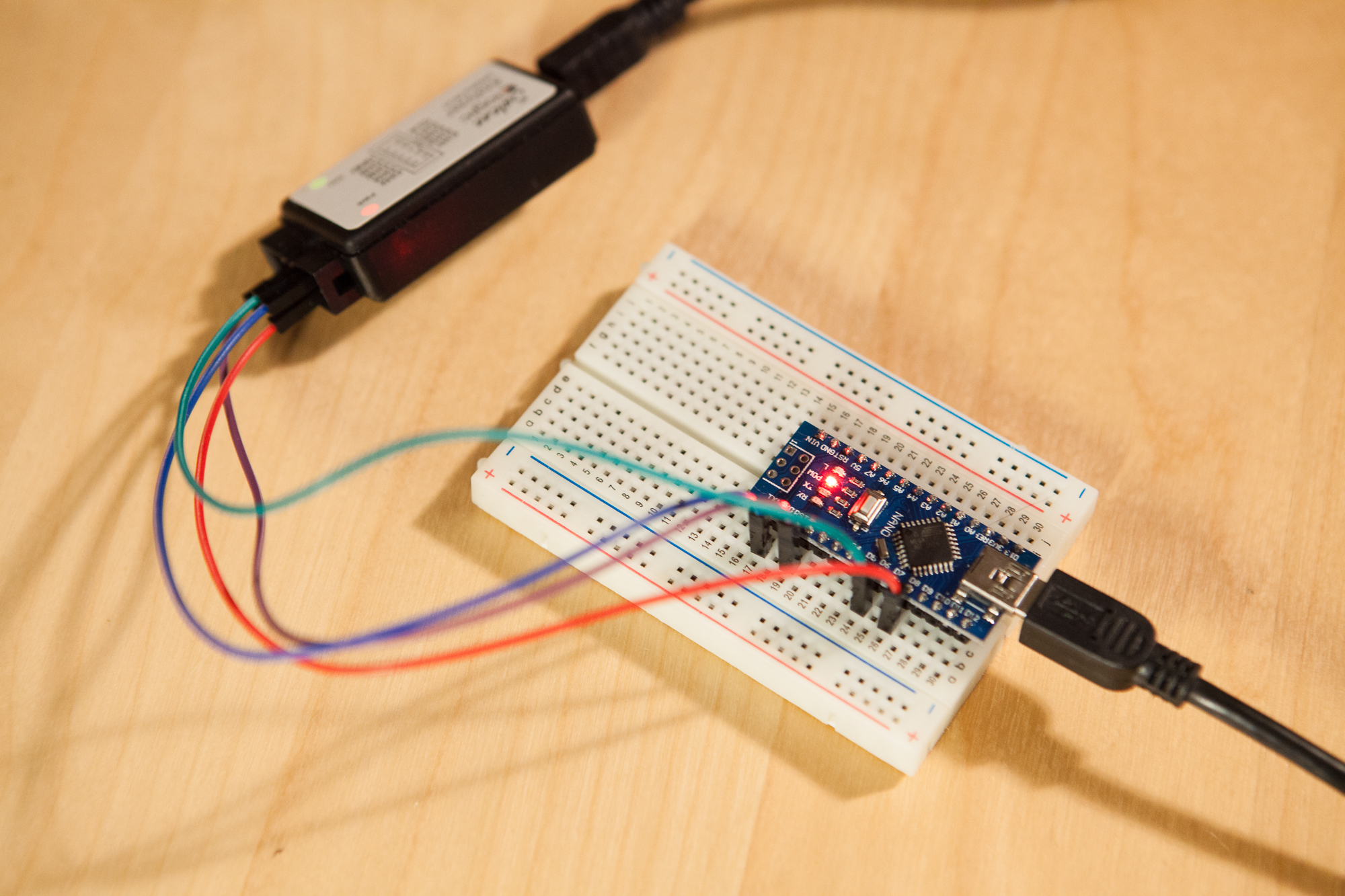
The first step to getting the ambient lighting system up and running is to test that our LEDs work as intended. I ordered a 5m roll of WS2812B LEDs from China, which have 60 LEDs per meter. Five meters is far more than I need for this project, but a roll was so cheap I couldn’t resist. After verifying that the LEDs worked with a FastLED example sketch, I uploaded the WS2812B Adalight sketch to the Arduino. The next step was to get the PC software working.
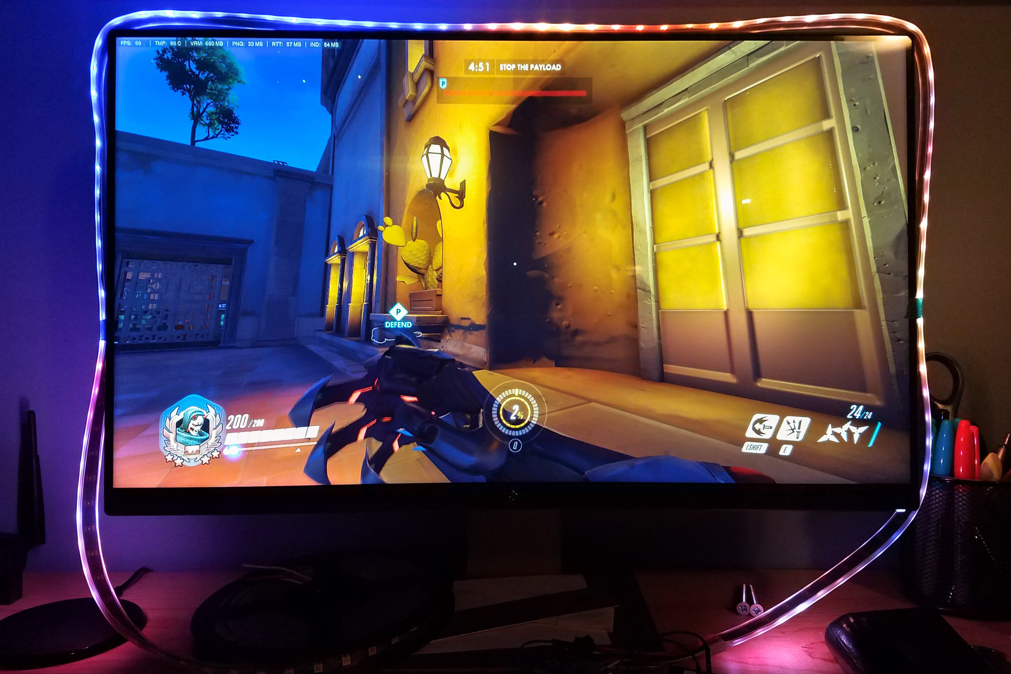
For their implementation Adafruit used a Processing sketch, but by all accounts it was slow and clunky. Instead, I found an open source software called Prismatik which supports the Adalight protocol. As it turns out the Prismatik software is also quite buggy, but at least it’s fast and lightweight. After installing Prismatik and throwing together a configuration for the Arduino (mostly noting the correct serial port and number of LEDs), I loaded up Overwatch and gave it a spin.
It works! The “white” produced by the RGB LEDs is very blue, made worse by the blue wall behind the monitor. Fortunately Prismatik has options for calibrating the color so I won’t need to do any scaling on the Arduino itself. No use messing with calibration until the LEDs are installed in their final position, so that’s it for today’s testing.
Next up: Part 2 – Prepping the WS2812B Strip

15 Comments
Mason · April 16, 2017 at 7:47 am
wow you are awesome ! i really appreciate and enjoy reading this project. This is by far the best tutorial for Arduino based ambient light on the internet, its well written and informative. Im going to build my own ambient light after finish reading your tutorial….. keep up the good work.
Dave · April 17, 2017 at 4:16 pm
Thanks Mason! I appreciate it.
Ian · October 5, 2017 at 1:53 pm
Hey, I’m trying to replicate your results, but after I install Prismatik, upload your code to Arduino and set up the FastLED library, nothing happens. Not sure how to make Arduino collect color data, I gathered it should do it automatically, as in your code makes sure it actually takes the data Prismatik captures. Or am I mistaken, and i need to manually ‘link’ my Arduino with Prismatik (already specified the correct port during config wizard).
Dave · October 5, 2017 at 6:25 pm
You also need to double-click the icon so the lights turn on. If the icon turns into a red ‘No’ symbol then there’s a communication problem (wrong port or port blocked).
Run at least one FastLED test sketch on the Arduino to make sure the lights work as intended (pin number, type, length, color order, etc.) before you start debugging the Prismatik side (COM port, baud rate, ‘Adalight’ protocol, etc.).
Ryan · November 14, 2017 at 5:45 am
Hi Dave,
I have a question before I delve into this guide. I’m thinking about adding this to a 4K monitor? Will all of the parts you used be compatible with my 4K monitor at 60HZ?
Dave · November 14, 2017 at 6:03 am
Hi Ryan. All of the hardware should be compatible, although a user on GitHub said that they’re having problems with Prismatik and their 4k monitor (another user said it worked fine, so take that with a grain of salt). It’s easy enough to test, though: install the software and give it a try with a “virtual” LED device.
Jamer Lino · March 28, 2018 at 8:43 pm
Greetings, first of all I must congratulate you for this great guide, what you have done is beautiful.
I have followed step by step the indications of this tutorial, and in principle all good, but I would like to know if it is normal that after a few seconds of inactivity in the computer the LEDs turn off, and they are reactivated when I press a key or move the mouse.
Dave · March 28, 2018 at 10:52 pm
That’s a setting in Prismatik. Under the “Experimental” category, disable the setting to “Send data only if colors changed”. You can also disable the serial timeout entirely in the Arduino code, but you will need to turn the lights off manually every time.
Jamer Lino · March 28, 2018 at 11:11 pm
You are definitely the best.
I appreciate the help, and I repeat, I have replicated what you have done and I am in love with the result.
Den Green · December 11, 2018 at 11:44 am
Sorry to post to an old thread, firstly I would like to ask about how many lights is the limit because I bought 144leds/m and in total, I would like to hook up 2 or 3 of these around my monitor, that totals for about 300 leds.I tried to do it but I managed to fry my Arduino (it is a Chinese knock-off that I got for about 4bucks at aliexpress, but for the time being it worked fine).
1. Is this possible?
2.What power supply would I need?
3. Can the Arduino be connected to pc through a USB cable and hooked up to the power supply at the same time?
Dave · December 11, 2018 at 12:18 pm
In theory there is no limit. Practically though you’re limited by your power supply, the RAM of the microcontroller, and the throughput of the virtual serial bus. I recommend keeping things under ~120 LEDs in total to keep things manageable. You can definitely do more but the cons tend to outweigh the pros. The LEDs blend before they hit the wall so you won’t get much in terms of “resolution” with the greater count, and the addressable LEDs are *really* bright. For my 24″ monitor with 80 LEDs (60/m) I run them at 70% max brightness. If you check out the project page I have a few posts covering the framerate limits as well.
In short:
1. Yes.
2. A beefy one (budget a minimum of ~60 mA per LED). E.g. 300 LEDs * 60 mA = 18A.
3. Usually no (depends on the board). You would power the Arduino via USB, power the LEDs with a standalone supply, and then share the grounds.
Den Green · December 13, 2018 at 10:02 am
Thank you for a reply, I have searched a bit and I found a power supply that has 90W 5V 18A and since I really know little about electricity I would like to ask if it is not going to burn down my house :D.
You also mentioned about microcontrollers RAM, so I found arduino DUE which is way more powerful from what I gathered, would it be an overkill or should I just stick to UNO?
And lastly, since my LEDs are very close apart I don’t really know how to split them normally and manage to ”wrap” them around my monitor and not get to the 300`s of them.
Dave · December 13, 2018 at 10:25 am
Golden rule of DIY electronics: if it looks scary and you have to ask whether it’s going to burn down your house, you probably shouldn’t be doing it :P. As with everything else, it’s perfectly safe if you know what you’re doing. It’s when you don’t know what you’re doing that you can get in trouble. Most of the commonplace standalone high amperage 5V supplies are made by… less than reputable dealers. Another reason I recommend keeping the LED count low.
Re: the RAM – use the Arduino IDE and try to compile my sketch for the Uno and your number of LEDs. It will yell at you if you’re running low on memory. The absolute max limit is somewhere in the ballpark of 600. RAM-wise the Uno should be fine with 300.
I would suggest ditching the 144/m strips altogether and buying some less-dense ones. Otherwise you can either split each LED separately and space them (a *lot* of work), or cut them into groups of 5-6 and space those (less work, but also less coverage).
Katper · December 18, 2019 at 7:20 am
i Just made it and its really looking awesome but i have a problem!
Some leds wont respond according to color pixels in screen, i looked closely at them they do turn on but have very low brightness and wont change color correctly. So what could be the reason??
I am using 104 Leds setup and 6A external power adapter.
Dave · December 18, 2019 at 12:17 pm
I would recommend trying one of the basic FastLED demo sketches to rule out any issues with the screen grabbing software and communication to the Arduino. If that still doesn’t work properly, I’d use a multimeter to check if those LEDs are suffering from voltage drop.