I’ve been messing around with MIDI for my musical floppy drive project, and it was surprisingly difficult to find detailed information on how to get started with Arduino’s MIDI library. So in this post I’m going to show you, in detail, how to use this library to control anything on an Arduino using MIDI.
What is MIDI?
MIDI, an acronym for Musical Instrument Digital Interface, is a protocol and interface standard designed to allow musical instruments and computers to connect and communicate with each-other. It’s widely used in the music world, for everything from digital audio workstations (DAWs) to musical keyboards. See the Wikipedia article for more information on the standard.
How do you use it?
The two most basic MIDI messages are “note on” and “note off” messages, that either start or stop a musical note. These messages have three parts:
- Channel: A channel between 1 – 16 that the note is played on. You can think of these as “tracks” for different instruments. Notes can be on any channel, although channel 10 is usually reserved for percussion.
- Note: The note being played, from 0 – 127 where 60 is middle C. Each increment is a semitone.
- Velocity: The speed at which the note is played, from 0 – 127. Think of it as the difference between hitting a piano key very quickly (high velocity) vs slowly pressing it until it plays the note (low velocity).
There are also a number of other messages, such as pitch bends and continuous controllers, that give you more control over how the instrument plays music (or, in this case, anything!).
So why is this useful with Arduinos?
The obvious reason is that you might be trying to make a musical instrument of some sort – a keyboard, a synthesizer, or something completely unique. But because you can use MIDI to control practically anything, there are some other reasons that may not be so obvious.
Timing Control
MIDI is designed for music, which means it is fundamentally intertwined with time. This means you can build a MIDI track on your computer and use it to control exactly when events will happen on a microcontroller without worrying about tedious (and much more permanent) delay timing.
You can also link many devices together with MIDI, and keep them all in sync with each-other while performing tasks.
MIDI Controllers
These days you can buy all sorts of MIDI controllers, from large digital keyboards to control boards and sample pads. These devices provide you with a whole host of polished physical controls for your devices that can be remapped, interlinked, and activated remotely.
Universal Support
If you need a remote control protocol for anything, MIDI might be a tempting candidate because it is so widely supported. Anything that uses an on/off switch or a potentiometer can be set up for MIDI control with just a few lines of code.
Instead of designing your own custom protocol, it may be easier just to adapt MIDI for your needs.
Getting Started
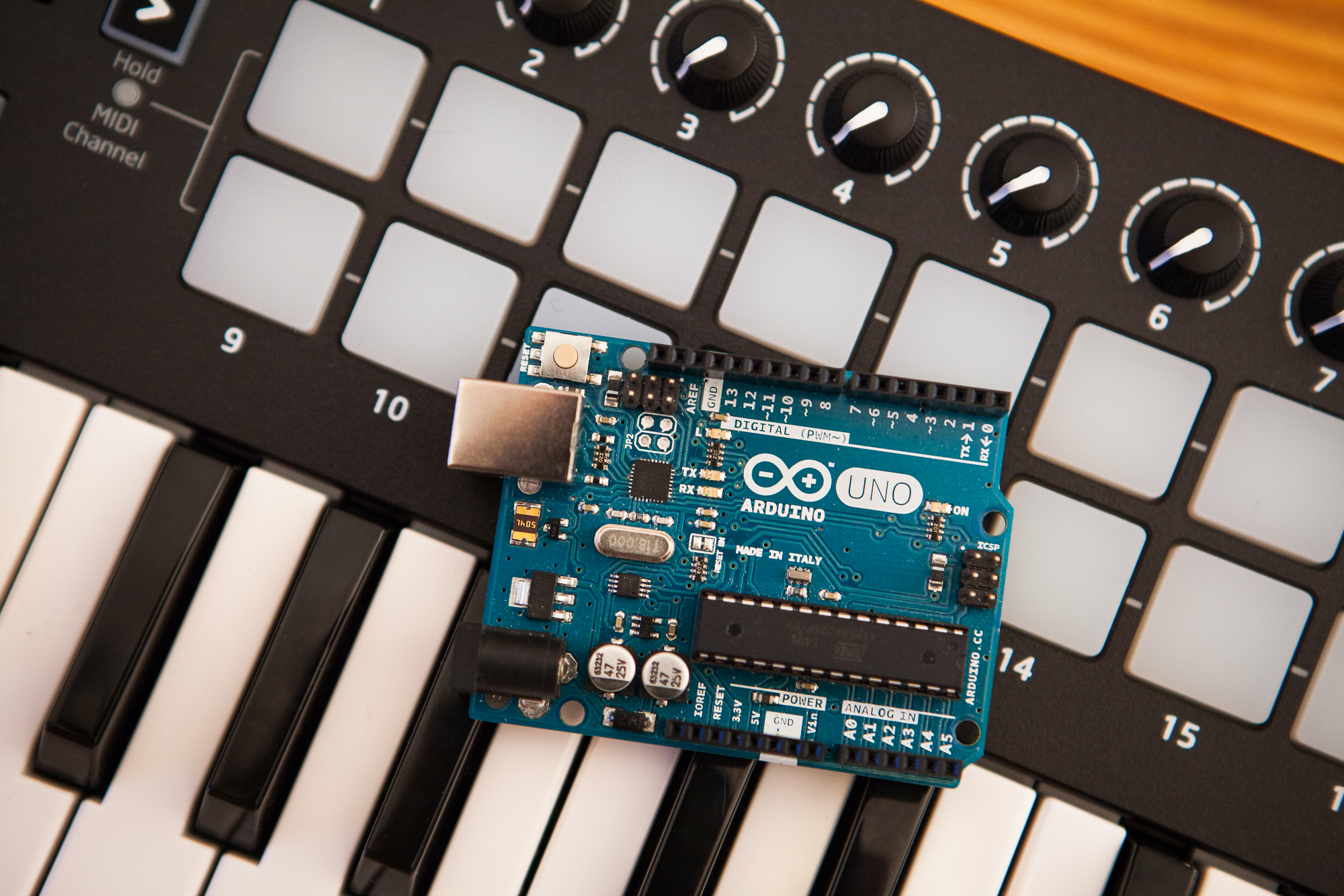
To do this you’ll need an Arduino of some sort – it doesn’t need to be a model with native USB support (e.g. Leonardo, Pro Micro), although it certainly doesn’t hurt.
The first thing you’ll need to do is to download the Arduino MIDI library by FortySevenEffects, which you can find here. You can also download it in the Arduino IDE by going to the library manager and searching for “MIDI”. Download the ZIP file and extract the contents into your Arduino ‘libraries’ folder.
Note: You don’t need to use the Arduino MIDI library to work with MIDI Messages, although it certainly does make things easier. If you’re writing your own MIDI code, I highly recommend this tutorial on the protocol.
Creating the MIDI Instance
Before we can do anything with MIDI, we need to create a MIDI instance so the Arduino knows where and how to get its MIDI data.
This can be as easy as this one line of code:
MIDI_CREATE_DEFAULT_INSTANCE();
This will build the typical MIDI instance usually used on your Arduino board. If you want to customize the parameters, you have a two options:
MIDI_CREATE_INSTANCE(Type, SerialPort, Name);
MIDI_CREATE_CUSTOM_INSTANCE(Type, SerialPort, Name, Settings);
Where:
- Type is either “HardwareSerial” or “SoftwareSerial” depending on the port type.
- SerialPort is the name of the serial port from the Arduino’s Serial class
- Name is the name of the MIDI port you’re creating. This can be anything you’d like.
- Settings is a custom struct from the MIDI library that contains the settings for a few custom parameters including baud rate.
To change the “settings”, you need to create your own struct:
struct MySettings : public midi::DefaultSettings{
    static const bool UseRunningStatus = false;
    static const bool HandleNullVelocityNoteOnAsNoteOff = true;
    static const bool Use1ByteParsing = true;
    static const long BaudRate = 31250;
    static const unsigned SysExMaxSize = 128;
};
Any values you put in this struct will overwrite the defaults. If you omit any, the struct will use the default values from the library.
Here are a few instance examples:
// Default Instance
MIDI_CREATE_DEFAULT_INSTANCE();

// Hardware Serial
MIDI_CREATE_INSTANCE(HardwareSerial, Serial, MIDI2);

// Hardware Serial, Custom Baud
struct CustomBaud : public midi::DefaultSettings{
    static const long BaudRate = 115200; // Baud rate for hairless
};
MIDI_CREATE_CUSTOM_INSTANCE(HardwareSerial, Serial, MIDI3, CustomBaud);

// Software Serial
#include <SoftwareSerial.h>
SoftwareSerial mySerial(10, 11); // RX, TX
MIDI_CREATE_INSTANCE(SoftwareSerial, mySerial, MIDI4);

// Dual Instance (Arduino Mega)
MIDI_CREATE_INSTANCE(HardwareSerial, Serial, MIDI5);
MIDI_CREATE_INSTANCE(HardwareSerial, Serial1, MIDI6);
For more information on instance creation, look at the source files for the MIDI definitions and MIDI settings in the library’s repository.
Adding Handler Functions
Once your instance is created, the next step is to link some handler functions. The MIDI library works by calling a function pointer when it finds a matching MIDI packet. Here is a list of the available handlers:
setHandleNoteOff(void (*fptr)(byte channel, byte note, byte velocity));
setHandleNoteOn(void (*fptr)(byte channel, byte note, byte velocity));
setHandleAfterTouchPoly(void (*fptr)(byte channel, byte note, byte pressure));
setHandleControlChange(void (*fptr)(byte channel, byte number, byte value));
setHandleProgramChange(void (*fptr)(byte channel, byte number));
setHandleAfterTouchChannel(void (*fptr)(byte channel, byte pressure));
setHandlePitchBend(void (*fptr)(byte channel, int bend));
setHandleSystemExclusive(void (*fptr)(byte * array, unsigned size));
setHandleTimeCodeQuarterFrame(void (*fptr)(byte data));
setHandleSongPosition(void (*fptr)(unsigned beats));
setHandleSongSelect(void (*fptr)(byte songnumber));
setHandleTuneRequest(void (*fptr)(void));
setHandleClock(void (*fptr)(void));
setHandleStart(void (*fptr)(void));
setHandleContinue(void (*fptr)(void));
setHandleStop(void (*fptr)(void));
setHandleActiveSensing(void (*fptr)(void));
setHandleSystemReset(void (*fptr)(void));
You configure these in the setup function, like so:
// "MIDI" is the name of our MIDI instance

void setup(){
  MIDI.setHandleNoteOn(noteOn);
  MIDI.setHandleNoteOff(noteOff);
  MIDI.begin(MIDI_CHANNEL_OMNI);
}

void noteOn(byte channel, byte note, byte velocity){
}

void noteOff(byte channel, byte note, byte velocity){
}
You can name these functions whatever you’d like, although keeping descriptive names will make your code more readable. The library automatically populates the function parameters with the data it receives for each respective message.
At the end of the setup function you also need to call begin() before the library will start reading the incoming MIDI messages. begin() takes one parameter, which is the MIDI channel to listen to. You can use MIDI_CHANNEL_OMNI to listen to all channels at once. If you don’t provide a parameter it listens to channel 1 only.
Read MIDI Messages
The last and crucial step is to make sure you’re calling the library’s read function to parse any incoming MIDI data. Incoming data will be handled by the respective handler functions, but if you don’t call read the library won’t receive any data to process.
void loop(){
  MIDI.read(); // Check for MIDI messages every loop
}
Write Your Code!
With the instance created and the handlers in place, now you can write your code to be controlled by MIDI!
A Demonstration: MIDI Visualizer
To demonstrate, I’m going to write the code for a basic MIDI visualizer that uses my favorite WS2812B addressable LEDs. The goal is to have LEDs on the strip correspond to different notes on the keyboard so they light up when a key is pressed, and turn off when the key is released.
To make it slightly more interesting, we can map some continuous controllers to change the colors on the fly.
Custom Instance
This visualizer is going to use an Arduino Uno, which doesn’t have native USB support. To get around this I’m going to use the Hairless MIDI to Serial Bridge to convert the MIDI messages into generic serial messages. You can see this post for more information.
For Hairless we’re going to change the Arduino’s baud rate from 31250 to 115200, which requires a custom MIDI instance:
struct CustomBaud : public midi::DefaultSettings{
    static const long BaudRate = 115200;
};
MIDI_CREATE_CUSTOM_INSTANCE(HardwareSerial, Serial, MIDI, CustomBaud);
Adding Handlers
This visualizer makes use of three MIDI messages: note on, note off, and continuous controller:
void setup(){
  MIDI.setHandleNoteOn(handleNoteOn);
  MIDI.setHandleNoteOff(handleNoteOff);
  MIDI.setHandleControlChange(handleControlChange);
  MIDI.begin(MIDI_CHANNEL_OMNI);
}
The “note on” and “note off” functions will mirror each-other: we’re going to check if the note is in the range we can play, set the LED color, and then refresh the LED strip.
const uint8_t minNote = 40;
const uint8_t maxNote = minNote + NumLEDs;

void handleNoteOn(byte channel, byte note, byte velocity){
  if(note < minNote || note > maxNote){
    return;
  }

  ledON(note - minNote);
  show();
}

void handleNoteOff(byte channel, byte note, byte velocity){
  if(note < minNote || note > maxNote){
    return;
  }

  ledOFF(note - minNote);
  show();
}
To control this visualizer I’m going to use a Novation Launchkey Mk II, which is a class compliant MIDI controller and has 8 rotary potentiometers that act as continuous controllers. These potentiometers are mapped to MIDI controller numbers 21 through 28, respectively.
I’m going to use the first three potentiometers to adjust the LED color channels: red, green, and blue. The code uses a switch() statement to check if the received control number matches one of the three color controls. If it does, the value from the controller is remapped from the MIDI range of 0 – 127 to the 8-bit range 0 – 255, and then the LEDs are updated.
const uint8_t
 redCC = 21,
 greenCC = 22,
 blueCC = 23;

uint8_t
 rVal = 255,
 gVal = 255,
 bVal = 255;

void handleControlChange(byte channel, byte number, byte value){
  switch(number){
    case redCC:
      rVal = map(value, 0, 127, 0, 255);
      redraw();
      break;
    case greenCC:
      gVal = map(value, 0, 127, 0, 255);
      redraw();
      break;
    case blueCC:
      bVal = map(value, 0, 127, 0, 255);
      redraw();
      break;
  }
}
LED Functions
Since I did my testing with an RGBW strip, I’ve written the code to work with both the Adalight NeoPixel and FastLED libraries. To keep the code clean, the specific library functions are encapsulated in their own helper functions.
I’m also using a boolean array to keep track of whether an LED is on or not for the redrawing function. This could be made more efficient, but for this example there’s plenty of memory available on the microcontroller.
// Build the LED strip
#ifdef ADAFRUIT_NEOPIXEL_H
  Adafruit_NeoPixel strip = Adafruit_NeoPixel(NumLEDs, Pin, NEO_GRBW + NEO_KHZ800);
#elif FASTLED_VERSION
  CRGB leds[NumLEDs];
#endif

boolean ledState[NumLEDs];

void ledON(uint8_t index){
  ledState[index] = 1;
  setLED(index, rVal, gVal, bVal);
}

void ledOFF(uint8_t index){
  ledState[index] = 0;
  setLED(index, 0, 0, 0);
}

void setLED(uint8_t index, uint8_t r, uint8_t g, uint8_t b){
  #ifdef ADAFRUIT_NEOPIXEL_H
    strip.setPixelColor(index, r, g, b);
  #elif FASTLED_VERSION
    leds[index].r = r;
    leds[index].g = g;
    leds[index].b = b;
  #endif
}

void redraw(){
  for(int i = 0; i<NumLEDs; i++){
    if(ledState[i] == 1){
      ledON(i);
    }
  }
  show();
}

void show(){
  #ifdef ADAFRUIT_NEOPIXEL_H
    strip.show();
  #elif FASTLED_VERSION
    FastLED.show();
  #endif
}
Result
Voilà! With just a few lines of code and the Arduino’s MIDI library, I built a basic MIDI visualizer with colors you can tweak via MIDI continuous controllers. Cool, huh?
Here is the full sketch, if you’d like to replicate this yourself. You can also find it on Github.
/*
 * Basic MIDI Visualizer
 * by David Madison © 2017
 * www.partsnotincluded.com
 *
 * This is a basic MIDI visualizer using addressable LEDs, to demonstrate how
 * Arduino's MIDI library works. Playing a note turns an LED on, stopping a note
 * turns the LED off. Continuous controllers 21, 22, and 23 adjust the RGB color.
 *
 */

#include <FastLED.h>
//#include <Adafruit_NeoPixel.h> // Uncomment if you're using RGBW LEDs

// ---- User Settings --------------------------
#define DATAPIN 6
#define NUMLEDS 60
#define BRIGHTNESS 255
#define BAUDRATE 115200 // For Hairless
#define NOTESTART 40
// ----------------------------------------

// Continuous Controller Numbers
static const uint8_t
  redCC   = 21,
  greenCC = 22,
  blueCC  = 23;

// Settings
static const uint8_t
  Pin = DATAPIN,
  NumLEDs = NUMLEDS,
  minNote = NOTESTART,
  maxNote = minNote + NumLEDs,
  maxBright = BRIGHTNESS;

// LED Color Values
uint8_t
  rVal = 255,
  gVal = 255,
  bVal = 255;

// Build the LED strip
#ifdef ADAFRUIT_NEOPIXEL_H
  Adafruit_NeoPixel strip = Adafruit_NeoPixel(NumLEDs, Pin, NEO_GRBW + NEO_KHZ800);
#elif FASTLED_VERSION
  CRGB leds[NumLEDs];
#endif

boolean ledState[NumLEDs];

// Create the MIDI Instance
#include <MIDI.h>
struct CustomBaud : public midi::DefaultSettings{
    static const long BaudRate = BAUDRATE;
};
MIDI_CREATE_CUSTOM_INSTANCE(HardwareSerial, Serial, MIDI, CustomBaud);

void setup(){
  #ifdef ADAFRUIT_NEOPIXEL_H
    strip.setBrightness(maxBright);
    strip.begin();
    strip.show();
  #elif FASTLED_VERSION
    FastLED.addLeds<WS2812B, Pin, GRB>(leds, NumLEDs);
    FastLED.setBrightness(maxBright);
    FastLED.show();
  #endif

  MIDI.setHandleNoteOn(handleNoteOn);
  MIDI.setHandleNoteOff(handleNoteOff);
  MIDI.setHandleControlChange(handleControlChange);
  MIDI.begin(MIDI_CHANNEL_OMNI);
}

void loop(){
  MIDI.read(); // Check for MIDI messages every loop
}

void handleNoteOn(byte channel, byte note, byte velocity){
  // Check if note is in range
  if(note < minNote || note > maxNote){
    return;
  }

  ledON(note - minNote);
  show();
}

void handleNoteOff(byte channel, byte note, byte velocity){
  // Check if note is in range
  if(note < minNote || note > maxNote){
    return;
  }

  ledOFF(note - minNote);
  show();
}

void handleControlChange(byte channel, byte number, byte value){
  switch(number){
    case redCC:
      rVal = map(value, 0, 127, 0, 255);
      redraw();
      break;
    case greenCC:
      gVal = map(value, 0, 127, 0, 255);
      redraw();
      break;
    case blueCC:
      bVal = map(value, 0, 127, 0, 255);
      redraw();
      break;
  }
}

void ledON(uint8_t index){
  ledState[index] = 1;
  setLED(index, rVal, gVal, bVal);
}

void ledOFF(uint8_t index){
  ledState[index] = 0;
  setLED(index, 0, 0, 0);
}

void setLED(uint8_t index, uint8_t r, uint8_t g, uint8_t b){
  #ifdef ADAFRUIT_NEOPIXEL_H
    strip.setPixelColor(index, r, g, b);
  #elif FASTLED_VERSION
    leds[index].r = r;
    leds[index].g = g;
    leds[index].b = b;
  #endif
}

void redraw(){
  for(int i = 0; i<NumLEDs; i++){
    if(ledState[i] == 1){
      ledON(i);
    }
  }
  show();
}

void show(){
  #ifdef ADAFRUIT_NEOPIXEL_H
    strip.show();
  #elif FASTLED_VERSION
    FastLED.show();
  #endif
}
Note that WS2812B LEDs are a poor choice for this because you’ll lose data during the LED latching, which can cause LEDs to be “stuck” on until they receive a MIDI off packet. But they’re one of the most common addressable LED types, and I still had plenty left over from the ambilight project.
Conclusion
This post is meant to be a primer – there is much more to MIDI and the Arduino’s MIDI library that I didn’t have time to touch on, notably how to send data back over MIDI. But hopefully you learned how to get started with the library and how to use MIDI data in your code.
For my example I used some addressable LEDs, but this can truly be used to control absolutely anything – servo motors, relays, speakers, serial messages… the list goes on and on. If you can control it with an Arduino and receive serial data, you can control it with MIDI.
If this tutorial helped you to build something controlled with MIDI, I’d love to see what you’ve come up with!