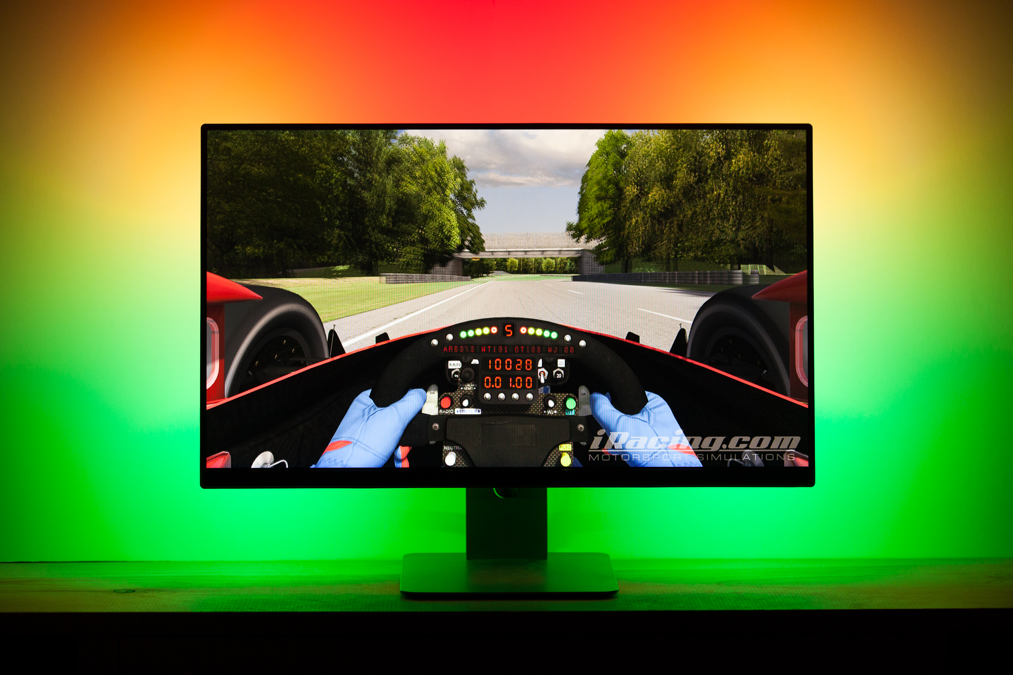
As I do more and more coding for the Footwell NeoPixels project, my mind started to wander with ideas of what else I could use addressable LEDs for. One such idea is to create an ‘ambilight’ – a backlight for a TV or LCD monitor that reads the color data onscreen and creates a glow around the bezel which matches or ‘extends’ the color to the surrounding wall. The idea is that it adds ambiance (hence the name), though it also helps with eye strain by reducing the contrast between the bright screen and the dark wall behind it. I had put a strip of single-color white LEDs behind my previous monitor and it helped tremendously with eye strain, but I figured if I was going to do the same I may as well take it up a notch.
This post is part of a series on creating a DIY ambilight using Adalight and WS2812B LEDs. Check out the project page here.
There are a couple of commercial products which do this, most notably Phillips’ line of Ambilight TVs. Because addressable RGB LEDs are now so commonplace and easy to use I figured there had to be a simple way to get the same result with any display. As it turns out I was right: in 2012 Adafruit developed a system which uses an Arduino as a middle-man to control a string of addressable LEDs. Their platform, dubbed ‘Adalight’, can run on any PC using a multimedia coding platform known as Processing. (There are also options for making an ambilight with a Raspberry Pi that is running as an HTPC, but only my PC is hooked up to this particular monitor).
The Adalight code is a bit dated however, and is designed to use WS2801 LEDs rather than the newer WS2812B. Compared to the slick 5050 integrated ‘NeoPixels’ we’re now used to, WS2801’s use an external control circuit to handle the signal processing. Newer WS2812B LEDs also use just three wires for control (power, data, and ground) while the WS2801’s require four wires (the three above + clock). The lack of external signal circuitry and needing one fewer wire means that WS2812B strips can have more LEDs per meter and are slightly smaller. They also require one fewer pin to control, although whether that makes them easier to use is debatable.
Before rewriting the code myself I did a cursory search and found that someone named James Bruce had already done the work for me! He tweaked the Adalight code to use the wonderful FastLED library for controlling the WS2812B strip. You can find his fork here.
Update 2017-04: I did eventually rewrite the code myself, fixing some bugs, improving the efficiency, and adding some additional features. You can download my version here.
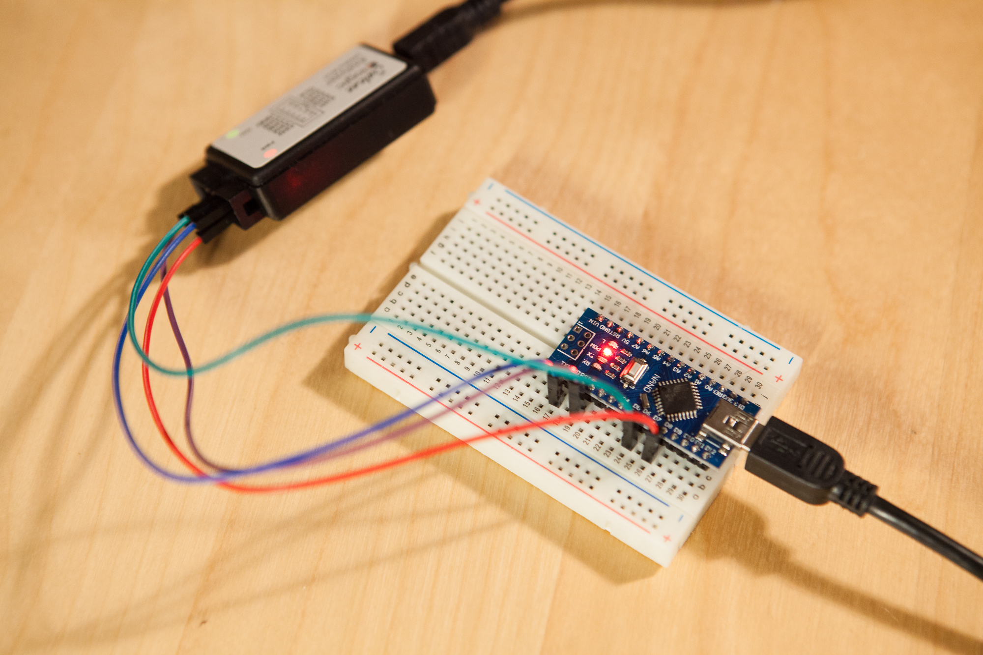
The first step to getting the ambient lighting system up and running is to test that our LEDs work as intended. I ordered a 5m roll of WS2812B LEDs from China, which have 60 LEDs per meter. Five meters is far more than I need for this project, but a roll was so cheap I couldn’t resist. After verifying that the LEDs worked with a FastLED example sketch, I uploaded the WS2812B Adalight sketch to the Arduino. The next step was to get the PC software working.
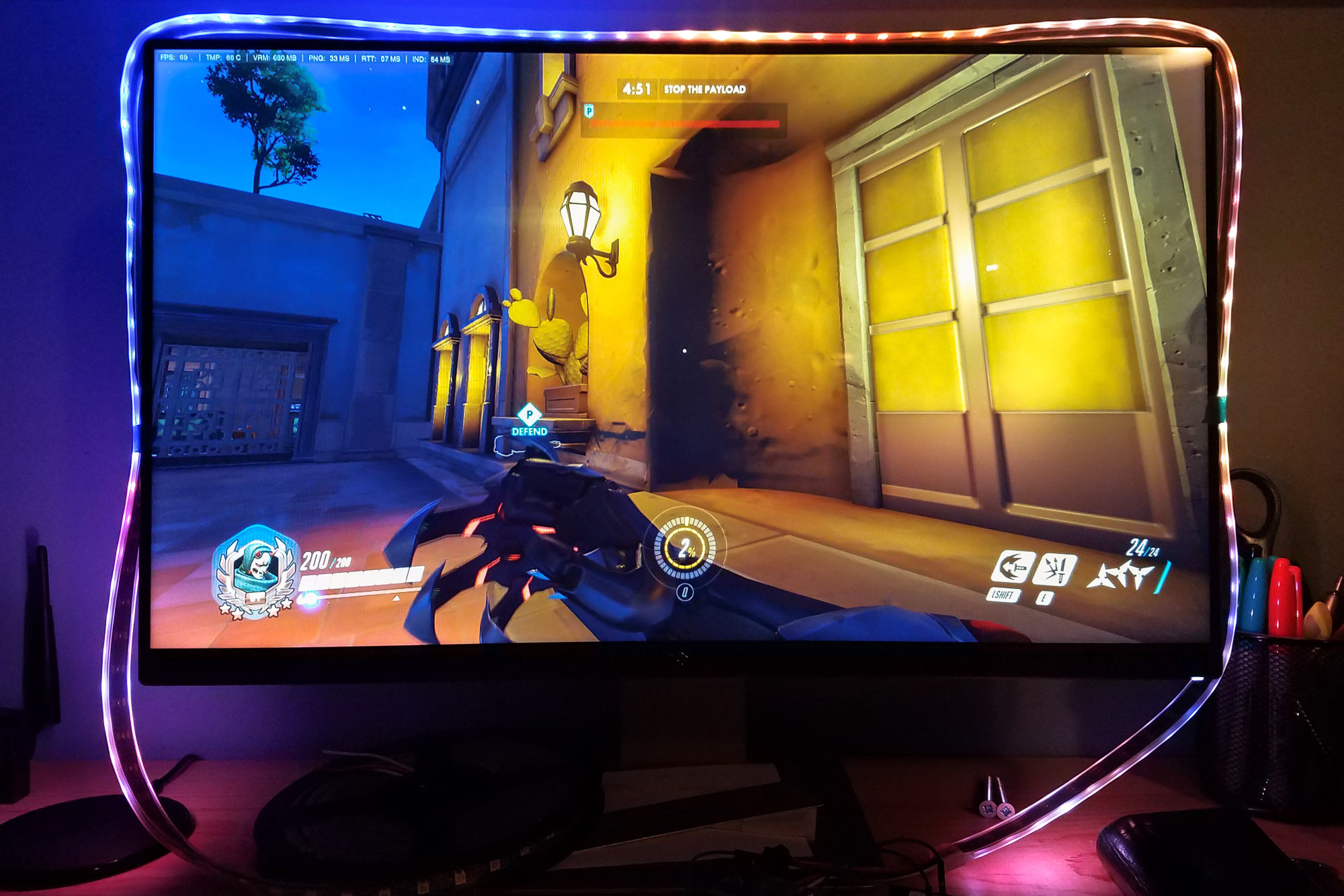
For their implementation Adafruit used a Processing sketch, but by all accounts it was slow and clunky. Instead, I found an open source software called Prismatik which supports the Adalight protocol. As it turns out the Prismatik software is also quite buggy, but at least it’s fast and lightweight. After installing Prismatik and throwing together a configuration for the Arduino (mostly noting the correct serial port and number of LEDs), I loaded up Overwatch and gave it a spin.
It works! The “white” produced by the RGB LEDs is very blue, made worse by the blue wall behind the monitor. Fortunately Prismatik has options for calibrating the color so I won’t need to do any scaling on the Arduino itself. No use messing with calibration until the LEDs are installed in their final position, so that’s it for today’s testing.
Next up: Part 2 – Prepping the WS2812B Strip