When the Nintendo Wii was released in 2006, there was a lot of talk about their new weird control system. In place of a typical control pad, players would use a one-handed “remote” with infrared sensors and accelerometers in place of a joystick. For those games that required additional controls, players would use an accessory controller in their off-hand.
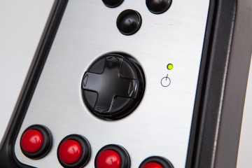
This ‘accessory’ controller is the Nunchuk. A strange, bean-shaped attachment with a joystick, two buttons, and a three-axis accelerometer. Although the Nunchuk had a lukewarm response when it was first released, it’s the perfect controller for makers who want to add some fine control to their projects.
In this tutorial I’m going to show you how to use a Wii Nunchuk with an Arduino: how to wire it, how to talk to it, and how to easily build programs using it and the NintendoExtensionCtrl library. Let’s get started!
Getting Connected
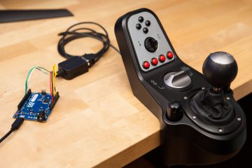
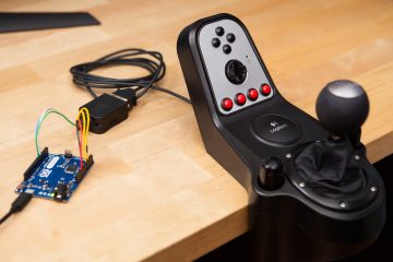
While the Wii remote itself is wireless, the Nunchuk was designed to plug into an accessory port at the bottom of the remote. This is actually better for DIY-ers, because it makes it easier to connect to a microcontroller.
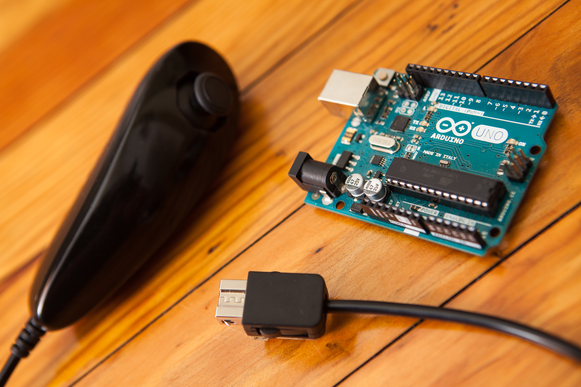
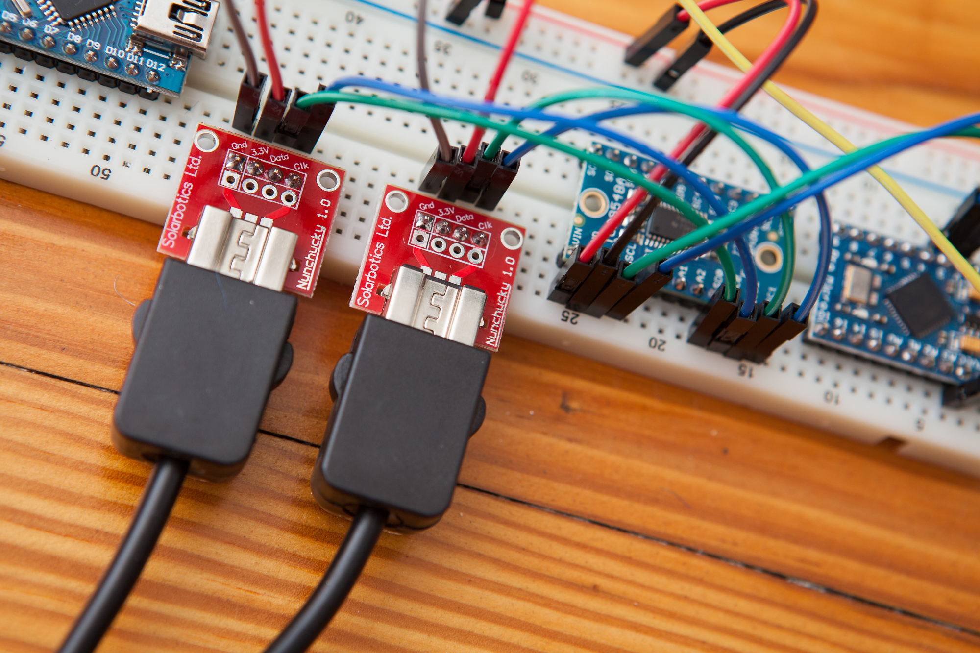
To connect to the Nunchuk I purchased a “Nunchuky” breakout board from Adafruit for a cool $3. The Nunchuk’s extension connector snaps right into the board, which exposes the power and data lines so I can plug it into a breadboard. You can also cut the connector off and use the bare wires, but there’s something to be said for keeping the controller intact.
From the Nunchuk’s 6-pin connector, these breakout boards expose 4 pins:
- Gnd: Ground.
- 3.3V: VCC
- Data: SDA, I2C serial data.
- Clk: SCL, I2C serial clock line.
Of the remaining two pins, one is not-populated on the connector and one is a power return used for controller detection. Unfortunately the breakout doesn’t expose this return pin, but you can solder to it if you need a controller-detect feature for your project.
Data Lines
As it turns out, the communication protocol used by the Nunchuk is none-other than standard I2C! Most microcontrollers have hardware support for I2C, so you can connect the data and clock lines from the Nunchuk directly to the supported pins on the microcontroller.
For the Arduino Uno, Nano, and other 328P-based boards the connection pins for SDA and SCL are A4 and A5, respectively. For the Arduino Leonardo and other 32U4-based boards, you use pins 2 and 3 for data and clock. If you’re not sure which pins to use, do a search for your microcontroller and “I2c”.
If you’re familiar with I2C, note that you do not need to add any pull-up resistors. The Nunchuk already has pull-up resistors onboard. (Or at least it should – some knockoffs are missing them!) You can test the pull up resistors yourself by measuring the resistance between one of the I2C wires and 3V3 while the controller is unplugged.
Voltage Levels
Power is trickier. The Wii remote operates at 3.3V, which means it outputs 3.3V to power the Nunchuk and pulls the I2C lines (data and clock) up to 3.3V when idle. Nunchuks are not designed to work with voltages over 3.3V, and higher voltages may damage the controller. This presents a problem for many Arduinos, the majority of which operate at a 5V logic level.
If your Arduino has a 3.3V regulator / pin, you should use that to power the Nunchuk (connecting to its ‘3V3’ pin). If your Arduino does not have a 3.3V regulator, such as with an Arduino Pro Micro, it’s highly recommended that you use a separate 3.3V regulator to power the Nunchuk.
Similarly, if your Arduino operates at 5V (Uno, Nano, Mega, Leonardo, etc.) and not 3.3V (Due, Zero) you should use a level shifter for the I2C data and clock lines. This prevents the Arduino from pulling the lines to 5V and makes the data stream more reliable. If your Arduino operates at 3.3V you can connect everything directly. (This is one of the reasons I recommend using a Teensy with a Nunchuk).
All of that being said, some Nunchuks appear to tolerate 5V. My Nintendo-made Nunchuks seem to work fine with an Uno and 5V power, while the third-party Nunchuks I have flip out and report bad data if the joystick is pushed too close to the edge. Your mileage may vary.
As with any electrical component, using a higher voltage level than expected – if it works at all – will usually lower the lifespan of the part. If your Nunchuk does work perfectly with +5V power, beware that it might fail prematurely.
Reading Nunchuk Data
With the Nunchuk connected to the Arduino it’s time to start reading data from the controller!
Thankfully a lot of smart people have messed around with these Wii extension controllers before me, so there is plenty of information online about how they work. After fighting with most of the existing libraries out there I decided to create my own called NintendoExtensionCtrl, which works with the Nunchuk and a few other controllers. You can download it from GitHub or by using the libraries manager in the Arduino IDE.
Setup and Initialization
Before we can start grabbing data from the controller we need to do a bit of setup. Create a new ‘sketch’ in the Arduino IDE, and at the top #include the NintendoExtensionCtrl library. Then create a new Nunchuk object that we’re going to call nchuk:
#include <NintendoExtensionCtrl.h>

Nunchuk nchuk;
Now at the start of the setup() function we’re going to initialize the I²C bus used by the Nunchuk by calling nchuk.begin(). This sets up the microcontroller’s hardware I²C functionality and prepares it to send and receive data from the controller. We’re also going to initialize the Serial bus so we can send mesages back to the PC and see what’s going on:
void setup() {
	Serial.begin(115200);
	nchuk.begin();
Last but not least we need to ‘connect’ to the controller. This library function initializes the controller in ‘unencrypted’ mode and retrieves the controller’s identity string. If the controller responds back, the function returns ‘true’ and we can start reading data! We’re going to stick this in a while loop so that the Arduino keeps trying to talk to the controller until it’s connected, and add a delay so it only tries once per second:
	while (!nchuk.connect()) {
		Serial.println("Nunchuk not detected!");
		delay(1000);
	}
}
Polling for Data
Because the Nunchuk works over the two-wire I2C bus, updates need to be polled from the device. Calling nchuk.update() requests 6 bytes of data from the controller. These 6 bytes contain all of the information for the Nunchuk’s controls.
If the update was successful, the function returns ‘true’. If it’s unsuccessful, the function returns ‘false’ and you may need to reconnect to the controller (connect() function, as above):
void loop() {
	boolean success = nchuk.update();  // Get new data from the controller
After updating with the most recent data, you can then retrieve the state of the Nunchuk’s controls. The library has built-in functions that do all of the bit-shifting and masking for you, and return the data either as an unsigned integer (joysticks / accelerometer) or as a boolean (button):
	if(success == true) {  // We have new data!
		nunchuk.update();

		nunchuk.joyX(); // 0 - 255
		nunchuk.joyY();

		nunchuk.accelX(); // 0 - 1023
		nunchuk.accelY();
		nunchuk.accelZ();

		nunchuk.buttonZ(); // 1 = On
		nunchuk.buttonC();
	}
}
For more examples of how these functions are used, check out the ‘Nunchuk_Demo’ example from the library.
Using Multiple Nunchuks
This is all fine-and-dandy for using a single controller, but what if you want to use two or more Nunchuks?
This is possible, but unfortunately it isn’t quite as easy. The system was designed to only use one device per Wii remote, and the limitation here is the I2C address.
The I2C bus used by the Nunchuk (and other extension controllers) is addressable. This means that it’s possible to have dozens of devices all communicating on the same bus using just two wires. To talk to a specific device the controller makes a request to that address. This is the problem, as all Wii extension controllers have the same address – 0x52. If you put two controllers on the same bus, they will both try to respond at the same time and you’ll have a conflict.
The solution is to use two I2C buses. Or, if you only have one bus on the microcontroller, to use an I2C multiplexer like the TCA9548A. Adafruit sells a nice breakout that works well. I’m currently using this multiplexer to have two Nunchuks work on an Arduino Pro Micro. It also conveniently acts as a level-shifter!
Example Project: LED Controller
Now it’s time to put this knowledge to work and make something! My typical go-to is something with RGB LEDs because they are quick to set up, have a lot of parameters, and offer clear visual feedback. As the Nunchuk is a controller, why not set it up to control a few LEDs?
I’m going to set this up as follows:
- Joystick X: Set number of LEDs (left to right)
- Joystick Y: Set brightness
- Accel XYZ: Set RGB values
- C Button: Flicker on/off
- Z Button: Turn on / off all
For my LEDs I’m going to use a small strip of WS2812B addressable LEDs, or what Adafruit calls “NeoPixels”. They’re inexpensive and easy to work with if you use a library like FastLED.
Setup
First a few housecleaning things. Import the NintendoExtensionCtrl and FastLED libraries, set a few global variables, and start both libraries in the setup function.
#include <NintendoExtensionCtrl.h>
#include <FastLED.h>

#define r 0
#define g 1
#define b 2

const uint8_t NumLEDs = 7;
const uint8_t LedPin = A0;

const uint8_t MinBright = 10;
const uint8_t MaxBright = 180;

uint8_t ledsOn = NumLEDs;

Nunchuk nunchuk;
CRGB leds[NumLEDs];

void setup() {
  FastLED.addLeds<WS2812B, LedPin, GRB>(leds, NumLEDs).setCorrection( TypicalLEDStrip );
  nunchuk.begin();
  while(!nunchuk.connect()){
    delay(1000);
  }
}

void loop(){
  clear(); // Clear LED data for new loop

  if(!nunchuk.update()){
    FastLED.show();  // write cleared LEDs
    delay(500);
    return;  // Bad data read
  }
  ...
}

void clear(){
  for(int i = 0; i < NumLEDs; i++){
    leds[i] = 0;
  }
}
Once we get to the loop, the code clears the LED data and polls the controller for new information. Each control is then handled in-turn.
JoyX: Number of LEDs
The ‘X’ value of the joystick controls how many LEDs are on. The value is divided by a parameter so the max possible value is the maximum number of LEDs in the strip.
ledsOn = nunchuk.joyX() / (255 / numLEDs);
This value is stored in a global variable. It’s going to be used to set the loop length when the LED colors are set.
JoyY: Brightness
The ‘Y’ value of the joystick controls the brightness of the LEDs.
uint8_t brightness = map(nunchuk.joyY(), 0, 255, MinBright, MaxBright);
The brightness is scaled depending on the ‘min’ and ‘max’ brightness values, set at the top of the code. This is just a quality of life thing – the LEDs can get crazy bright. It also works using the joystick value directly.
Accel XYZ: Color Values
The accelerometer values for X, Y, and Z control the RGB color of the strip.
void loop() {
  ...
  setColors(r, nunchuk.accelX());
  setColors(g, nunchuk.accelY());
  setColors(b, nunchuk.accelZ());
  ...
}

void setColors(uint8_t rgb, uint16_t val){
  if(rgb >= 3) return;

  for(int i = 0; i < ledsOn; i++){
    leds[i].raw[rgb] = val / 4;
  }
}
The accelerometer value is 10 bits (0 – 1023), so it’s divided by 4 to get an 8-bit value that fits in the array. The LEDs are assigned from the start of the strip through the number dictated by the ‘X’ joystick value stored earlier.
Z Button: Turn off
The large ‘Z’ button turns off the entire strip.
  if(nunchuk.buttonZ()){
    clear();
  }
This just calls the ‘clear’ function from earlier if the button is pressed. Nice and easy.
Z Button: Flicker
The smaller ‘C’ button makes the strip flicker.
void loop(){
  ...
  else if(nunchuk.buttonC()){
    blink(150);
  }
  ...
}

void blink(long blinkTime){
  static unsigned long lastMillis = 0;
  static boolean blinkState = 0;

  if(blinkState == true){
    clear();
  }

  if(millis() - blinkTime/2 >= lastMillis){
    blinkState = !blinkState;
    lastMillis = millis();
  }
}
The function takes a millisecond input of the total blinking period and flips a boolean every half period. If that boolean is true, the function clears the LEDs.
Writing to the Strip
At the end of the loop, the program updates the brightness and writes the LED data to the strip.
void loop() {
  ...
  FastLED.setBrightness(brightness);
  FastLED.show();
}
And just like that, I have a working LED controller from a Wii Nunchuk!
Here’s the full sketch. Click below to expand the code.
#include <NintendoExtensionCtrl.h>
#include <FastLED.h>

#define r 0
#define g 1
#define b 2

const uint8_t NumLEDs = 7;
const uint8_t LedPin = A0;

const uint8_t MinBright = 10;
const uint8_t MaxBright = 180;

uint8_t ledsOn = NumLEDs;

Nunchuk nunchuk;
CRGB leds[NumLEDs];

void setup() {
  FastLED.addLeds<WS2812B, LedPin, GRB>(leds, NumLEDs).setCorrection( TypicalLEDStrip );
  nunchuk.begin();
  while(!nunchuk.connect()){
    delay(1000);
  }
}

void loop() {
  clear(); // Clear LED data for new loop

  if(!nunchuk.update()){
    FastLED.show();  // write cleared LEDs
    delay(500);
    return;  // Bad data read
  }

  ledsOn = nunchuk.joyX() / (255 / NumLEDs);
  uint8_t brightness = map(nunchuk.joyY(), 0, 255, MinBright, MaxBright);

  setColors(r, nunchuk.accelX());
  setColors(g, nunchuk.accelY());
  setColors(b, nunchuk.accelZ());

  if(nunchuk.buttonZ()){
    clear();
  }
  else if(nunchuk.buttonC()){
    blink(150);
  }

  FastLED.setBrightness(brightness);
  FastLED.show();
}

void setColors(uint8_t rgb, uint16_t val){
  if(rgb >= 3) return;

  for(int i = 0; i < ledsOn; i++){
    leds[i].raw[rgb] = val / 4;
  }
}

void clear(){
  for(int i = 0; i < NumLEDs; i++){
    leds[i] = 0;
  }
}

void blink(long blinkTime){
  static unsigned long lastMillis = 0;
  static boolean blinkState = 0;

  if(blinkState == true){
    clear();
  }

  if(millis() - blinkTime/2 >= lastMillis){
    blinkState = !blinkState;
    lastMillis = millis();
  }
}
Conclusion
These are really cool little controllers, and they’re surprisingly easy to use with Arduino thanks to the I²C interface and the NintendoExtensionCtrl library.
Have you used a Nunchuk in your Arduino project? Share in the comments below!
Under the Hood
In case you’re curious or want to try this without using my library, let’s briefly cover how the Nunchuk I²C communication works at a lower level.
The following code snippets have been borrowed from the NintendoExtensionCtrl library and simplified for explanatory purposes. To look at what the library is actually doing, check out the communications header and the static communications functions.
Initialization
Before it will send any data, the Nunchuk needs to be initialized. The library makes this easy with a connect method, but let’s look at what’s going on under the hood.
boolean i2c_writeRegister(byte addr, byte reg, byte value) {
	Wire.beginTransmission(addr);
	Wire.write(reg);
	Wire.write(value);
	if (Wire.endTransmission() != 0) return false;  // 0 = No Error
	return true;
}

boolean ExtensionController::initialize() {
	if (!i2c_writeRegister(0x52, 0xF0, 0x55)) return false;
	delay(10);
	if (!i2c_writeRegister(0x52, 0xFB, 0x00)) return false;
	delay(20);
	return true;
}
The Nunchuk acts as a typical register-based I²C device. The library joins the hardware I2C bus as a master and then writes two bytes to the Nunchuk: 0x55 to register 0xF0, and 0x00 to register 0xFB. According to information I found online the Nunchuk normally encrypts its output using an XOR transformation. By initializing the device with these two commands, the Nunchuk operates in an “unencrypted communication mode”. This means the data it sends in response to a polling request, while bit-packed for transfer, is plainly formatted and easily parsed.
The connect() method for the library also has a function to identify what type of controller is connected, as the Wii remote’s port also supports other controllers like the Wii classic controller and musical instruments for games like Guitar Hero. The identity function requests 6 bytes from register 0xFA and then compares them against a known list. The Nunchuk, for example, is identified by the last two bytes being 0x00. See the library’s identity header for more info.
Control Data
boolean i2c_writePointer(byte addr, byte ptr) {
	Wire.beginTransmission(addr);
	Wire.write(ptr);
	if (Wire.endTransmission() != 0) return false;  // 0 = No Error
	delayMicroseconds(175);  // Wait for data conversion
	return true;
}

boolean ExtensionController::requestControlData(size_t requestSize, uint8_t* controlData) {
	if (!i2c_writePointer(0x52, 0x00)) return false;  // Set start for data read

	uint8_t nBytesRecv = Wire.readBytes(controlData,
		Wire.requestFrom(0x52, requestSize));

	return (nBytesRecv == requestSize);  // Success if all bytes received
}
To poll for an update, the Arduino first sends 0x00 to the Nunchuk to set the register pointer at the start of the data block. It then requests 6 bytes of data from the Nunchuk. These 6 bytes contain all of the information for the Nunchuk’s controls.
The data from the Nunchuk comes packaged in a specific way to save bandwidth on the bus. This allows Nintendo to squeeze a little more range out of the accelerometer while keeping the max polling rate the same.
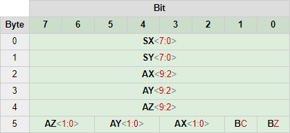
The first two bytes are the joystick X and Y values, respectively. The next three bytes are the most significant bits for the accelerometer values (XYZ). The last byte contains the two least significant bits for all three accelerometer values, as well as single bits for the on/off states of both buttons. These button values are inverted, so a ‘0’ means the button is pressed.
The bit-depth for the controls are as follows:
- Joystick XY: 8 bit (0 – 255)
- Accelerometer XYZ: 10 bit (0 – 1023)
- Buttons C/Z: 1 bit (0 – 1)
After retrieval from the bus the controls can be extracted by using bitshifting and masking on the data array.
This article contains affiliate links. As an Amazon Associate I earn from qualifying purchases.