It’s incredible how far display technology has come. Nowadays LED walls are found at every major concert venue, flat panel televisions are ubiquitous, and everyone has a high resolution, full color LCD display in their pocket. It’s difficult to imagine that just a few short decades ago it was a struggle to create a large, dynamic display for an economical price.
One such solution to that problem was “split-flap” displays. This technology was commonly used in train stations, bus terminals, and airports for arrival and departure boards – places where information is needed at a glance, clearly visible at all times of day, and easily updatable when schedules change. On a smaller scale it also made its way into consumer alarm clocks, one of which is immortalized in the film Groundhog Day (1993).
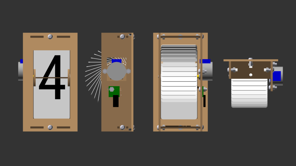
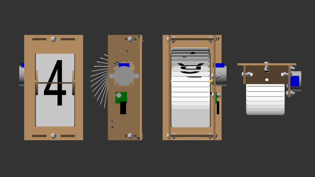
The displays themselves were mechanical in nature. A set of flaps was attached around a spool, each flap labeled with half of a character on either side. As the spool is rotated, the flaps successively flip forwards to change the character visible from the front. When a full character was displayed you’d see the front half of one flap and the back of another with a split in the middle – hence the name “split-flap”.
Recently there has been a resurging nostalgic interest in these displays. And I decided to build one for myself.
Project Outline
Instead of starting from scratch, I’m going to be using Scott Bezek’s excellent split-flap project as a base. About five years ago Scott also decided he wanted a set of split-flap displays, so he set about researching and creating a completely open source, low-cost DIY split-flap system:
The primary design goal was to make something that’s possible to fabricate at home in small or single quantities and can be customized and built by an intermediate hobbyist at a reasonable price. This meant using widely available materials and avoiding any tooling with a high upfront cost.
Scott Bezek, August 22, 2016
https://scottbez1.github.io/splitflap/
The project has four distinct parts that need to come together to make these displays work:
- The laser-cut enclosure, which holds the flaps and keeps everything together
- The plastic flaps and lettering, which provide the eponymous “split-flap” output
- The driver electronics, for positioning and spinning the split-flap spool
- The embedded programming, to translate characters and strings to motor commands for the flap spool
In this article, I’m going to go step by step through my process of modifying Scott’s project and building my own set of split-flap displays.
It’s worth emphasizing that Scott’s project is still a work in progress and has yet to be released as a stable version. My build is based roughly around commit 7f5a51b (closest full release, v0.7). Future readers (hello from the past!) may find that later versions may differ slightly or significantly. Feel free to leave a comment if you spot a discrepancy.
With that out of the way, let’s jump right in! Starting with the first section: the enclosure.
Enclosure
Following Scott’s low-cost and no-tooling design philosophy, the enclosure is composed entirely of laser-cut panels that notch together with tabs.
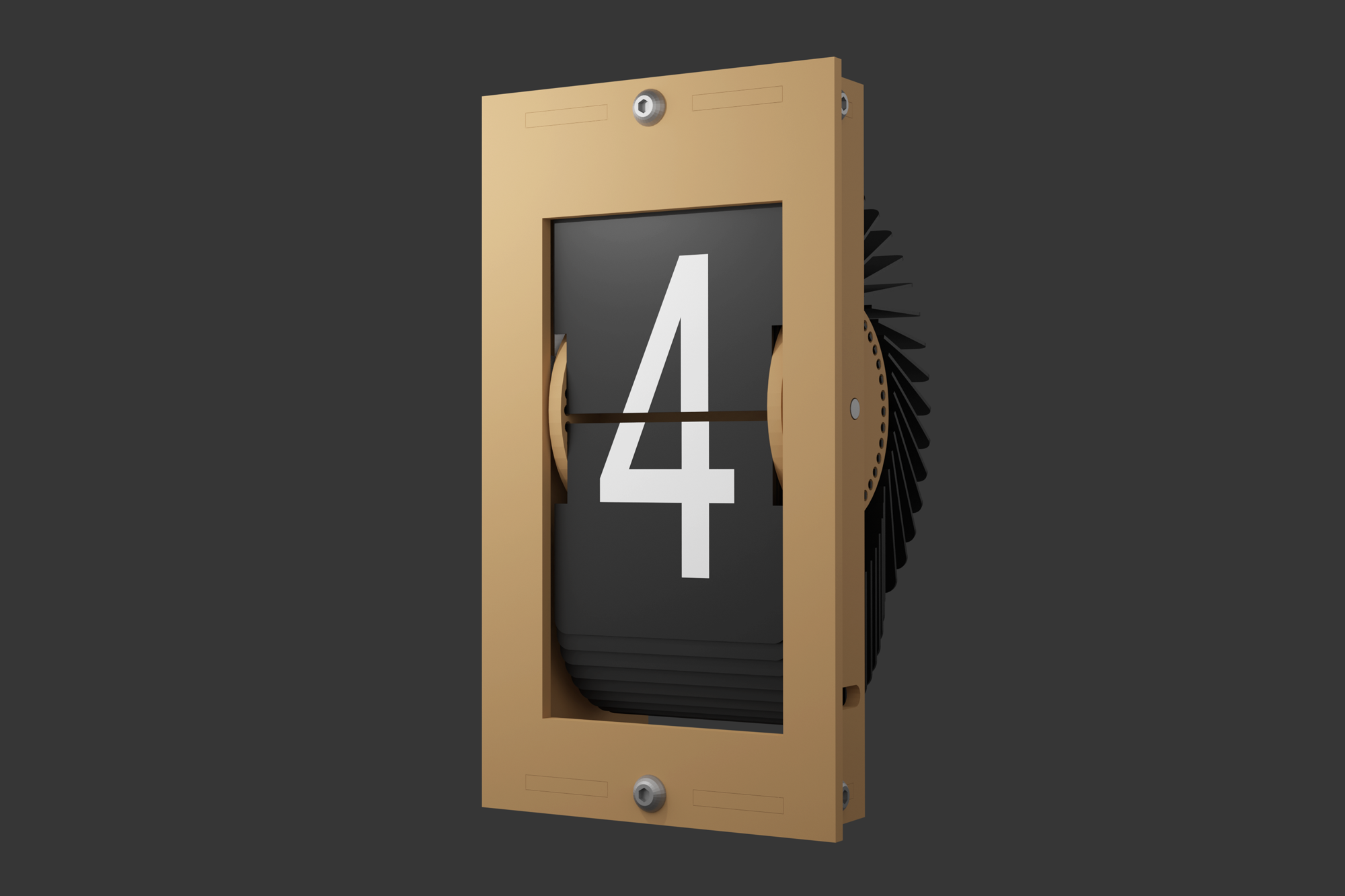
OpenSCAD Design
The entire flap display is designed in OpenSCAD, a 3D CAD modeling program that builds models using a functional programming language instead of a graphical editor. As Scott is a software engineer by day, he found the idea of creating 3D models by writing code to be quite appealing. After all, creating a 3D model entirely with code has some serious perks.
For one, the entire design is parametric – you can change values such as the the panel thickness or number of flaps and the entire design will be regenerated. Although fully parametric design is of course possible with other CAD packages using design tables or design-driven equations, OpenSCAD practically mandates this practice due to its programmatic design.
The functional programming also makes the design modular. Each part, offset, or feature can be rolled into its own geometric function (module) which can be duplicated or reused elsewhere in the assembly.
Not only is the design flexible, but OpenSCAD also lends itself well to automation. The split-flap project repository contains a number of Python scripts to automate outputs for the completed 3D design, including:
- Generating the 2D panel for lasercutting
- Offsetting geometry to compensate for a cutter’s kerf
- Creating an animated gif of the model
- Outputting STL versions of each part
- Calculating part colors for an 3D web viewer
And much, much more.
CAD Improvements
Scott did an amazing job putting the CAD assembly together, and I cannot stress enough how impossible it would have been to make this project a reality without his hard work. Still, there were some small changes to the design I wanted to make before I built my own enclosures.
Unfortunately the functional programming model used by OpenSCAD cuts both ways. As nice as it is to have a fully parametric model that lends itself well to automation, it’s a real pain to create geometry in OpenSCAD compared to most CAD programs. Features aren’t menu items but rather built from scratch using primitive geometry and functional programming. Although the changes I had planned were simple in concept, it took a significant amount of time and effort to wade through the nearly 2,000 lines of code which define the split-flap assembly’s geometry.
In total I submitted 33 pull requests to the project, of which a whopping 24 affected the enclosure assembly.
The most significant of these was overhauling how the panel thickness was handled in the assembly. When Scott built his first displays he used 3.2 mm (0.125″) MDF, which is soft and will deform if the panels are slightly off-sized. I was looking to build my displays out of 3.0 mm (0.118″) acrylic, which is a hair thinner and significantly more brittle. Unfortunately reducing the design’s thickness parameter even slightly caused a number of issues, including the front window narrowing beyond the width of the flaps. My submitted fix accounts for the width of the flaps and the size of the bolts, so the material thickness for the entire assembly can now be adjusted several millimeters in either direction without issue!
The rest of these changes were small polish fixes:
- Rounding the corners of the motor window and the sensor PCB cutouts
- Improving the placements of parts on the laser-cut panel
- Adding an etched ‘home’ flap indicator
- Adding alignment indicators for assembly
- Including zip-tie holes for wire management
That list doesn’t include some of the cosmetic tweaks, such as automatically calculating the assembly color variations and rendering all of the letters in the flap spool. It’s entirely possible that I may have gone a bit overboard in playing with the CAD code…
But all good things must come to an end. Once I was satisfied that the enclosure design was ready to go, it was time to export the 2D paths and move on to fabrication!
Ordering from Ponoko

I do not own a lasercutter myself, so I had to turn to an online lasercutting service: Ponoko!
I’ve used Ponoko in the past for other projects, including the LED standoffs for my time circuit displays. Their website is dirt simple to use: upload an SVG or DXF of your design, select the cut and etched geometry, choose your material, and place your order!
Each split-flap enclosure costs around $14 USD to manufacture, plus a setup fee per order (also, conveniently, $14). All modules were cut from glossy red acrylic, 3 mm thick.
Generating the SVG
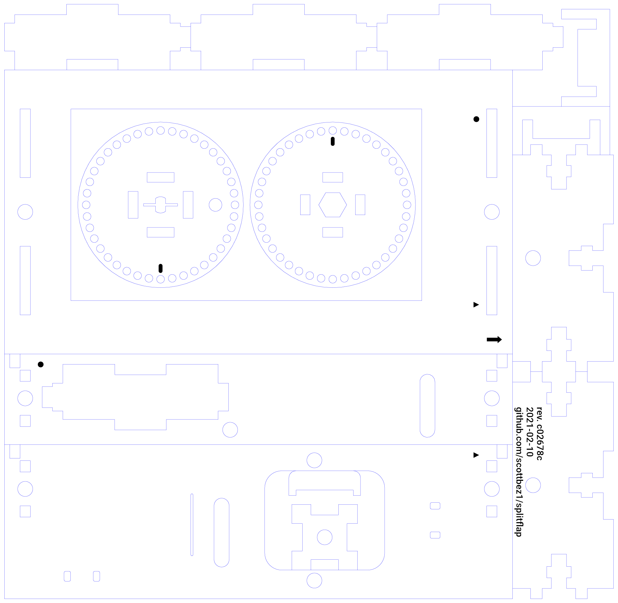
This is where the CAD automation for the split-flap project comes in handy. Running the generate_2d.py script outputs an SVG file with all of the enclosure parts organized for laser-cutting. The parts are arranged to take up the smallest possible area with duplicate cut edges removed. The script has a number of command line options to tweak the output, including:
--thicknessfor changing the panel thickness and associated geometry--kerffor adjusting the kerf compensation for the width of the laser--skip-optimizefor bypassing the optimization code that removes duplicate lines--panelizefor merging multiple copies of the design into one SVG
For the final version of my displays I used a --thickness of 3.0 mm and a --kerf of 0.1 mm.
Nailing Down Tolerances
I ended up having to order a few different enclosures while I was working out the kinks of the thickness and clearance values.
The first of these was made of 3.0 mm matte black acrylic using a kerf offset of 0.18 mm, slightly less than Ponoko’s listed kerf value of 0.2 mm. Although this should have been accurate per the specs, the resulting cut parts were all oversized by around 0.1 mm. While most joints fit together, the press-fit parts such as the homing magnet and the motor shaft caused the spindle to crack. The matte finish was also on the wrong side, as the 2D design has all of the outside faces facing down to prevent burn marks when the enclosure is cut out of the original material, MDF.
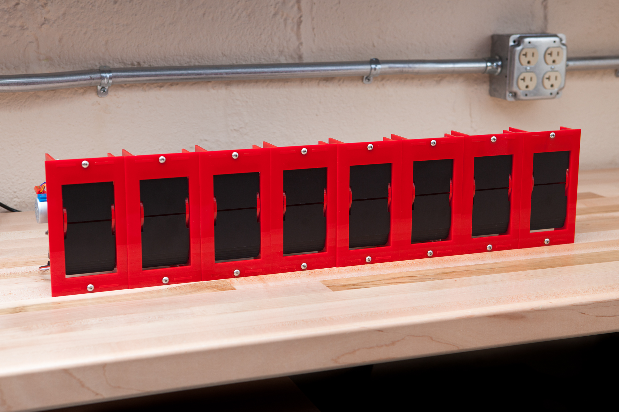
For the second order I backed off on the kerf compensation, down from 0.18 mm to 0.1 mm. I also switched up the color to a glossy red acrylic, which should “pop” more against the black and white flap design. The measurements for this order were right on spec, although the fitment for the spool’s parts was too loose and press-fit openings were too small. Thankfully this was a Goldilocks story, the third and final order of all 8 displays was just right.
(Okay maybe the third order actually had an issue with the spool slop that caused the flaps not to flip smoothly and I had to buy replacements, but isn’t it a better story if the third bowl of porridge wasn’t slightly undersized?)
Believe it or not, the enclosures were actually the last part in the project to come together – owing to the number of tweaks I wished to make to the design, the tolerance / kerf adjustments, and the long turnaround time from Ponoko for manufacturing. In total I placed 4 separate test enclosure orders before the final set of 8.
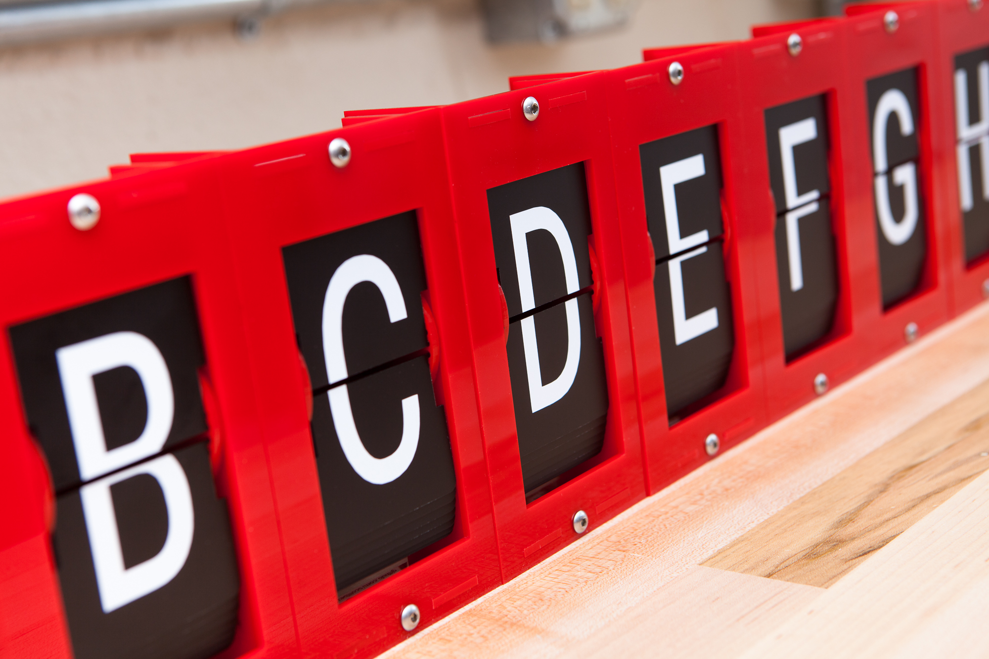
Flaps and Lettering

While I was waiting for the enclosure to be manufactured I decided to get a head start on the flaps. There are 40 flaps per module with half a letter on each side.
Die-Cut Flaps
In Scott’s original design the flaps were made out of blank CR80 cards: thin PVC cards the same size and thickness as an ID or credit card. The flaps would be made by scoring the cards and snapping them in half. Then you would use a badge slot punch on either side to create the pins and cutouts for the spindle.
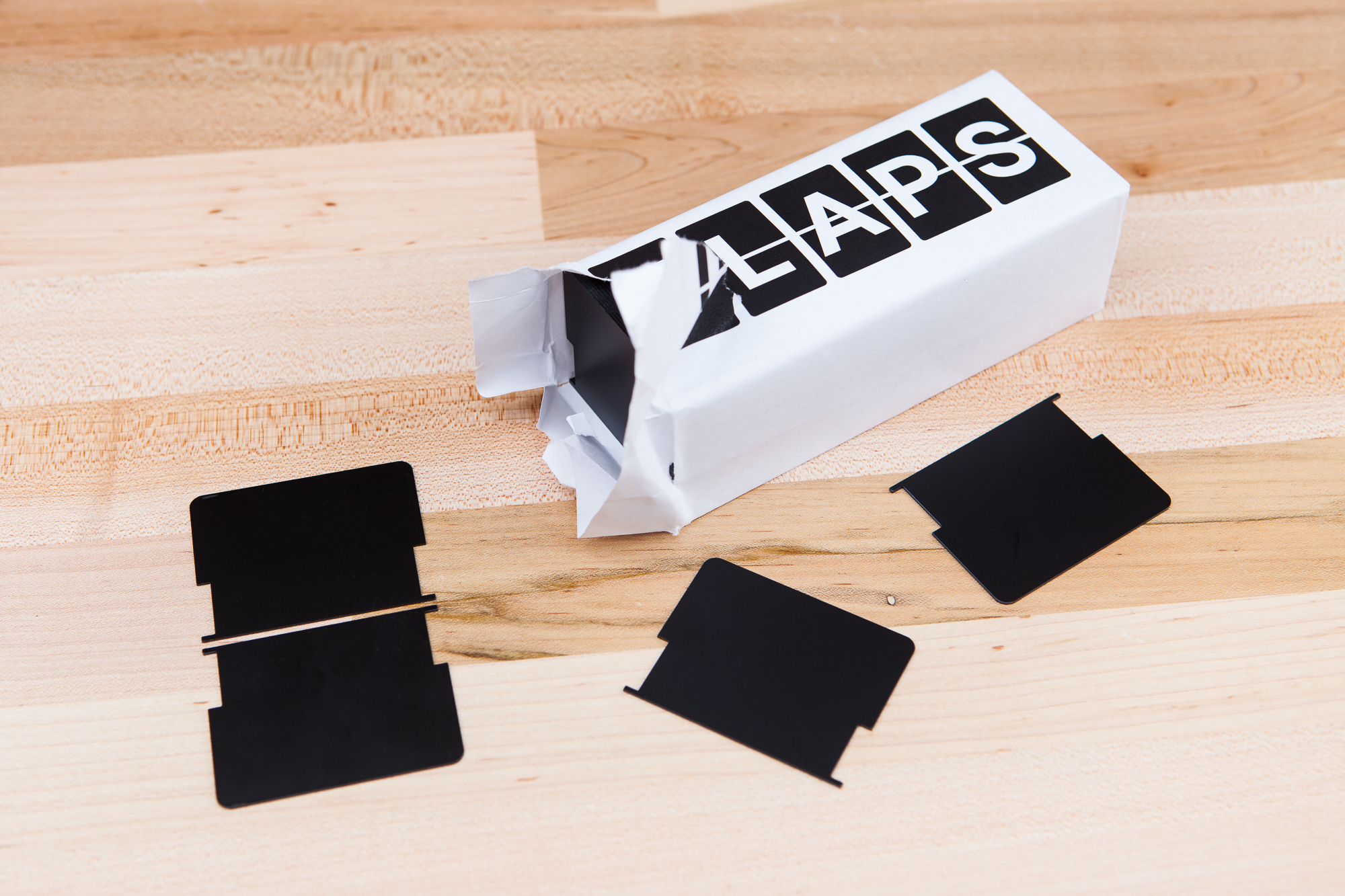
Needless to say this is time consuming, and the finished flaps are a little rough around the edges. To save time and create nicer finished modules, Scott had a bunch of die-cut flaps manufactured with the exact sizes needed for his project. And he sells them in sets of 160+ on Tindie! Enough for 4 modules with a few leftover.
I ordered two sets of flaps from Scott in black, enough for all 8 modules. These were definitely pricier than making them myself, but ordering them from Scott saved a lot of time, and the quality is unmatched. And most importantly it means the flaps are a smooth matte black, which frankly I just think is cooler and better fits the retro aesthetic.
Letter Generation
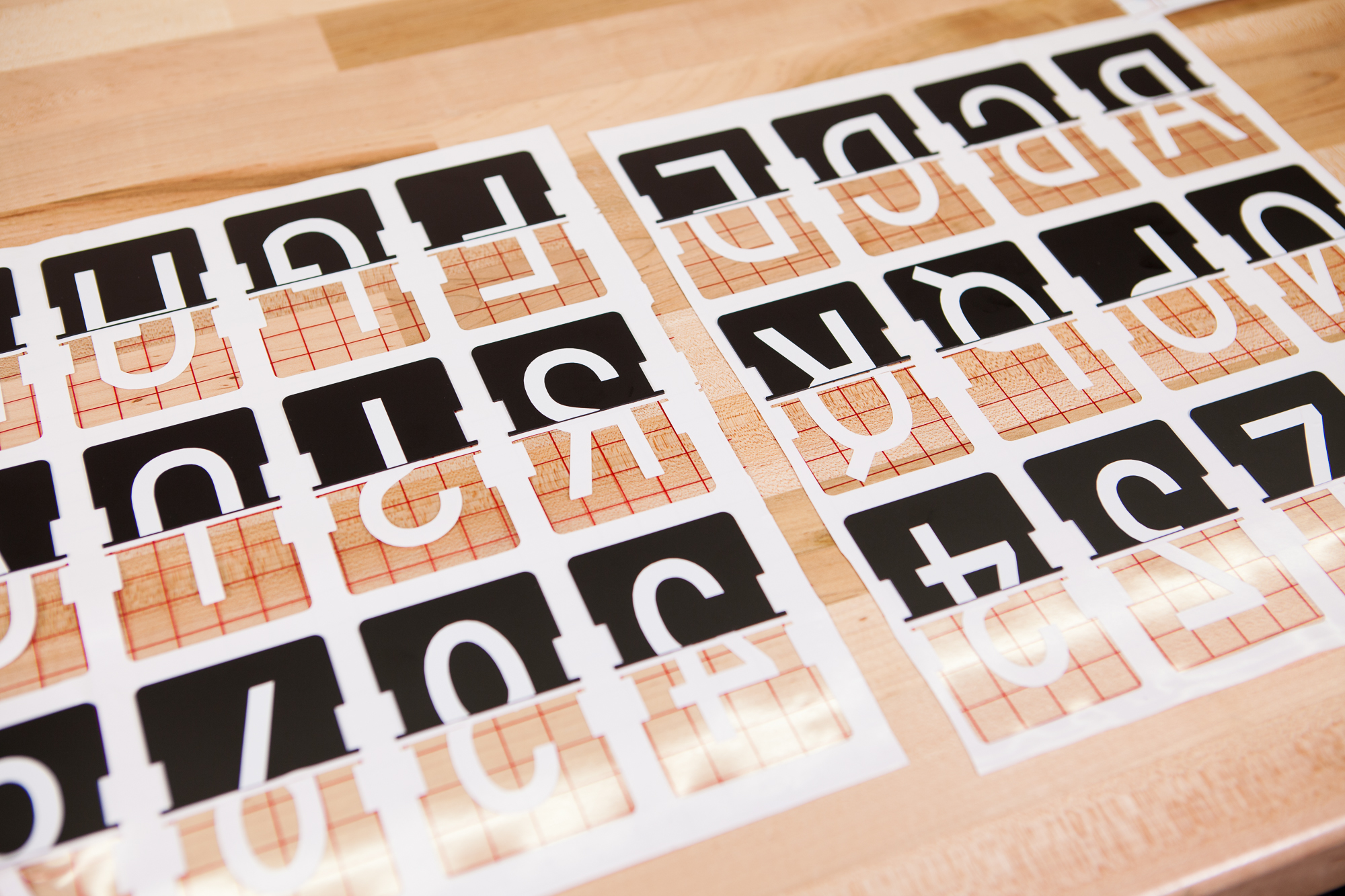
With flaps in hand the next step was to apply the vinyl letters to convert the blank flaps into the visual components of the display!
Scott’s original design uses packs of off-the-shelf vinyl letters. Each letter is applied across a pair of flaps and then cut down the middle. This is inexpensive, but has a few disadvantages: it doesn’t account for the gap between the flaps, the application process is slow, and you’re limited to what fonts and colors you can find in stores.
For my own displays I decided to go in a different direction. I have my own vinyl cutter, so I chose to generate and cut the flap letters myself. In theory this is faster, more accurate, and more flexible, as you can choose any font or vinyl color that you wish!

To make this possible I rewrote the project’s font generation code so that letters were correctly split and centered on each flap half, then created my own OpenSCAD design to generate an array of evenly spaced flaps with letters. I also created a complementary Python script to export the generated font letters to SVG format for cutting. The Python script has a number of options to tweak the output, including changing the font, the generated character string (“abcd” etc.), character size, character position, and the gap compensation between the top and bottom flaps.
Each split-flap module has 40 flaps and 40 possible characters it can display. Accounting for a blank character (‘ ‘), the 26 characters of the alphabet, and the 10 decimal numbers, that leaves 3 extra characters to choose. For my own display modules I decided to use ‘!’, ‘?’, and ‘+’. I’m also considering making a few extra flaps so I can swap these out if need-be.
The generation command I used, executed circa 7be69db, is as follows:
python scripts/generate_fonts.py -t "ABCDEFGHIJKLMNOPQRSTUVWXYZ0123456789!?+" --ncolumns 13
This creates a 3-row SVG with each letter inscribed inside of a pair of flaps, using the default sans-serif “Roboto” font. Now let’s cut them out!
Cutting Letters
Using Adobe Illustrator I converted the SVGs into DXF format and then imported the designs into Silhouette Studio for cutting on my Silhouette Cameo 3. Unfortunately as I don’t have a roller attachment I had some issues keeping the roll of vinyl straight, so I ended up splitting the design into 3 sheets of 4 or 5 columns each.
All of the letters were cut out of Oracal 631 matte white vinyl. This is so-called “indoor” vinyl, which means it uses a less tacky adhesive and can be removed without leaving a permanent residue (in theory, at least). I ended up using around 25 feet of vinyl for all 320 flaps (8 modules of 40 flaps each), including replacements from mistakes during application.
Once all of the letters were cut the design was weeded to remove the excess vinyl between the flap outlines and the characters. Then the designs were covered with transfer paper and readied for application.
Applying Letters
Once I had the vinyl sheets taped upside-down on my workbench and I carefully removed the vinyl’s backing. Although I had weeded the flap cutouts themselves I left the outlines – this way the negative flap areas can be used as alignment markers for the character application. Align the flap pins, carefully rotate the flap into place, press it down to make sure the vinyl is adhered, and then move on to the next.
The generated design has a full character in each cell, so instead of flipping flaps halfway through I just did two modules for each sheet. First, a full set of 80 blank flaps (40 for character tops, 40 for character bottoms) are applied to one letter sheet and removed. Then the back faces of those flaps are applied to the next sheet, offset by one character. This means each sheet will do one half of 2 sets of flaps, or 2 sheets will cover all characters for 2 modules.

When the first half of each flap set was removed I separated out the top and bottom letters into two stacks, being careful to keep them in the same order. For applying the second set the letters on the opposite face I only had to be mindful of the starting point: the flap with the upper part of ‘A’ is also the flap with the lower part of ‘B’ and vise-versa. Once I had that offset figured out and the first flap placed I just applied the flaps in the same order as they were taken off.
After all of the characters were applied, I went through each flap to trim tiny slivers of excess vinyl from the inside edge and check for bubbles or misaligned characters. I ended up replacing around 40 letter-halves out of a total of 640. Only a handful of those were flat-out unusable, the rest were to fix small inconsistencies and alignment issues.
All-in-all the application process worked great, although in hindsight it’s a far call from “fast”. If I had to make another set I might consider an alternate method, or perhaps design a proper jig to speed up the process.
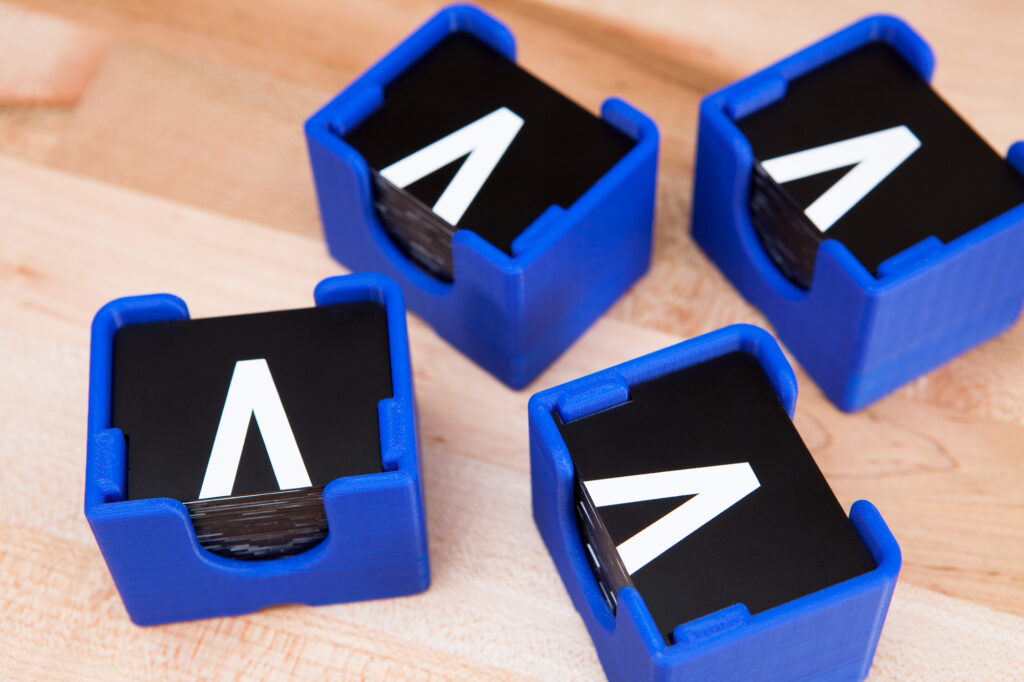
I designed and 3D printed a small container to keep the finished flaps safe until the enclosures were ready for assembly, then set them aside. The flaps will have to wait until the rest of the design is assembled and wired before they can be inserted into the spools.
Speaking of wiring…
Electronics
Next on the list are the electronics. These circuits drive the module motors and keep track of the spool’s position so you know which flap is being displayed at any moment in time.
There are three circuits that make up the display assembly: the module drivers, the home sensors, and the microcontroller which handles the program logic.
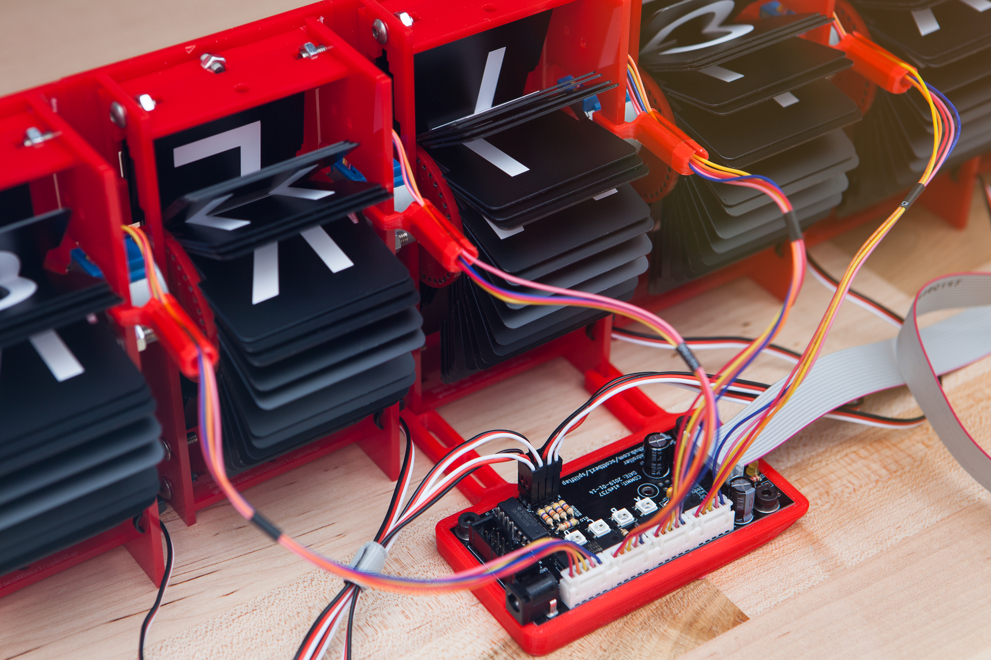
Module Driver
Attached to each module’s flap spool is a 12V 28BYJ-48 unipolar stepper motor, which Scott chose for its ubiquity and low cost. The control board’s job is to drive these motors and ingest the hall effect sensor data so the microcontroller can determine the position of the spools. Each board can drive 4 split-flap modules and also includes addressable WS2812B status LEDs for showing each module’s current state.
To control the motors, the board has two MIC5842 latched Darlington output drivers leading to four separate 5-pin JST XH headers which connect directly to the motor leads. The home sensors connect to a 74HC165N shift register, and each end of the PCB has a 7×2 IDC connector for chaining driver boards together. Motor power is provided through a barrel jack in the corner and transmitted to chained drivers through the expansion ports.
I purchased my 2 bare driver PCBs from Scott, who sells them on Tindie. In hindsight I probably should have ordered my own after making some modifications, but the boards function just the same.
The project includes an auto-generated bill of materials, extracted from the KiCAD board files and uploaded to Scott’s AWS account via a continuous integration script whenever a commit is made to the repository’s master branch. Pretty cool stuff!
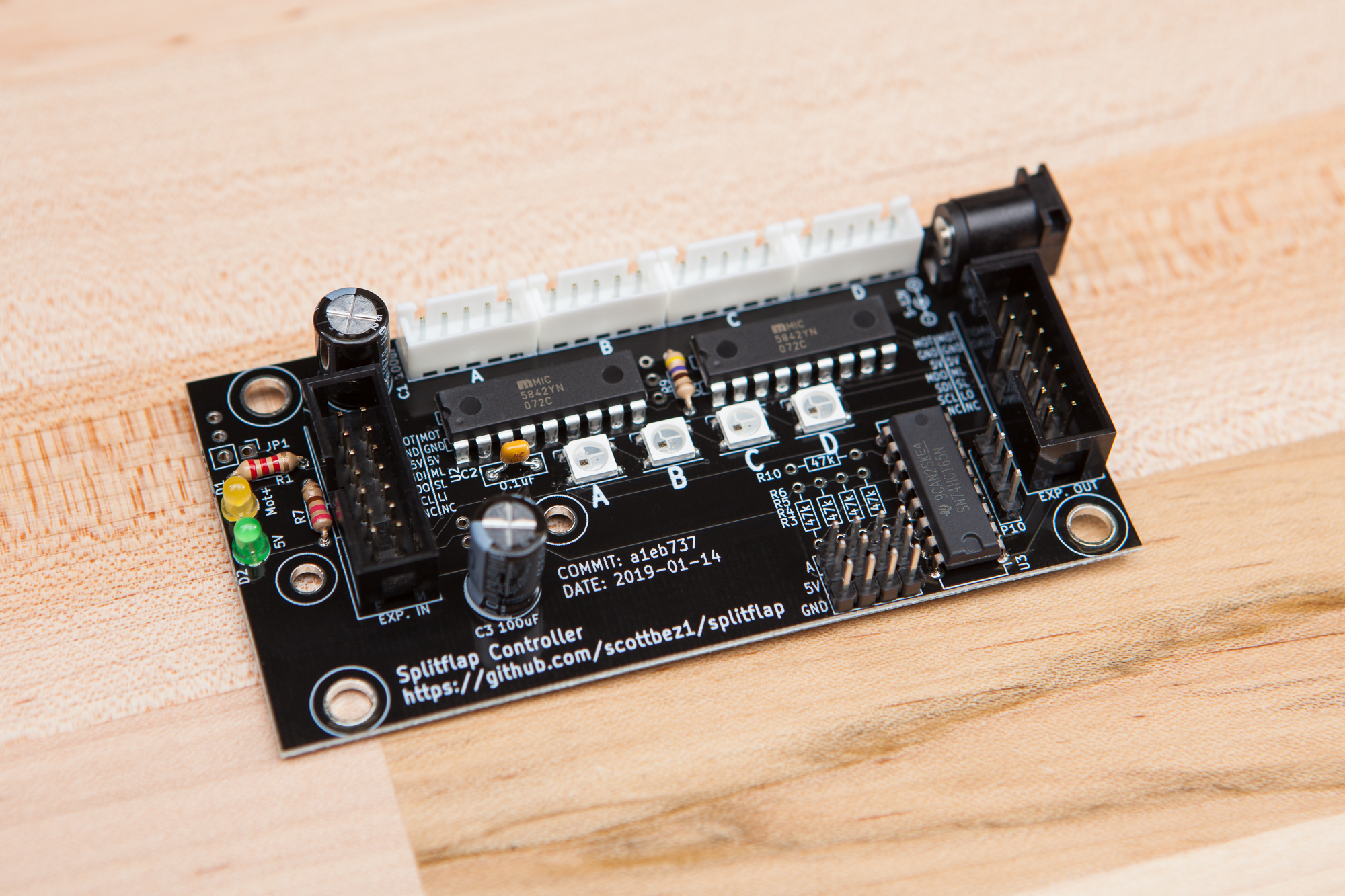
I ordered the full bill of materials from DigiKey and had no problems soldering them up. The addressable LEDs were attached with solder paste and hot air, then the rest of the through-hole components were soldered in the typical fashion. In his assembly guide Scott recommends adding and removing certain components to save on cost depending on whether the board will be the “main” driver (connected to the microcontroller) or a “secondary” driver (connected via the expansion ports). I wanted both boards to be interchangeable in case I wanted to have 2 sets of 4 modules in the future instead of 1 set of 8, so I soldered up all components to both – including the expansion slots at either end.
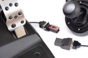
I purposefully chose not to solder on the headers to connect to the Arduino Uno, as I have other plans for the microcontroller interface and I didn’t want extra pins hanging down from the board. More on that in a bit.
Home Sensor
The split-flap modules use a hall effect based homing system. On the spool there is a 4 mm hole in which you press-fit a neodymium magnet. When the spool spins around this magnet is detected by a hall effect sensor on its own mini circuit board. The sensor sends a signal to a shift register on the driver board to tell it that the module has reached its home position.
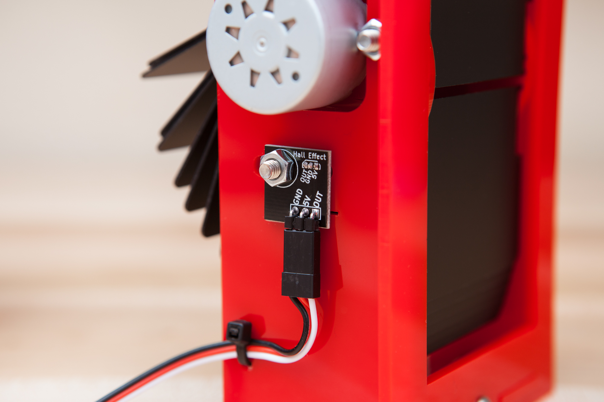
This home sensor circuit board is as simple as it gets. There is a 3-pin 0.1″ header, a 3 pin through-hole hall effect sensor, and a single M4 through-hole for mounting to the enclosure. As with the driver boards, I purchased all 8 sensor PCBs (unpopulated) from Scott on Tindie, and the pins and hall effect sensors from DigiKey.
The one catch with the sensor circuit boards is that the hall effect sensor isn’t soldered flat to the PCB like most through-hole components. Instead, the leads are bent at a 90° angle and the sensor is held several millimeters away from the board so it is closer to the spool and its homing magnet. To nail this offset I designed a small jig to sit between the PCB and the body of the sensor. This is cut out of the laser-cut panel alongside the rest of the enclosure, although I 3D printed mine early in this build before I had any enclosures in hand.
Microcontroller and Breakout
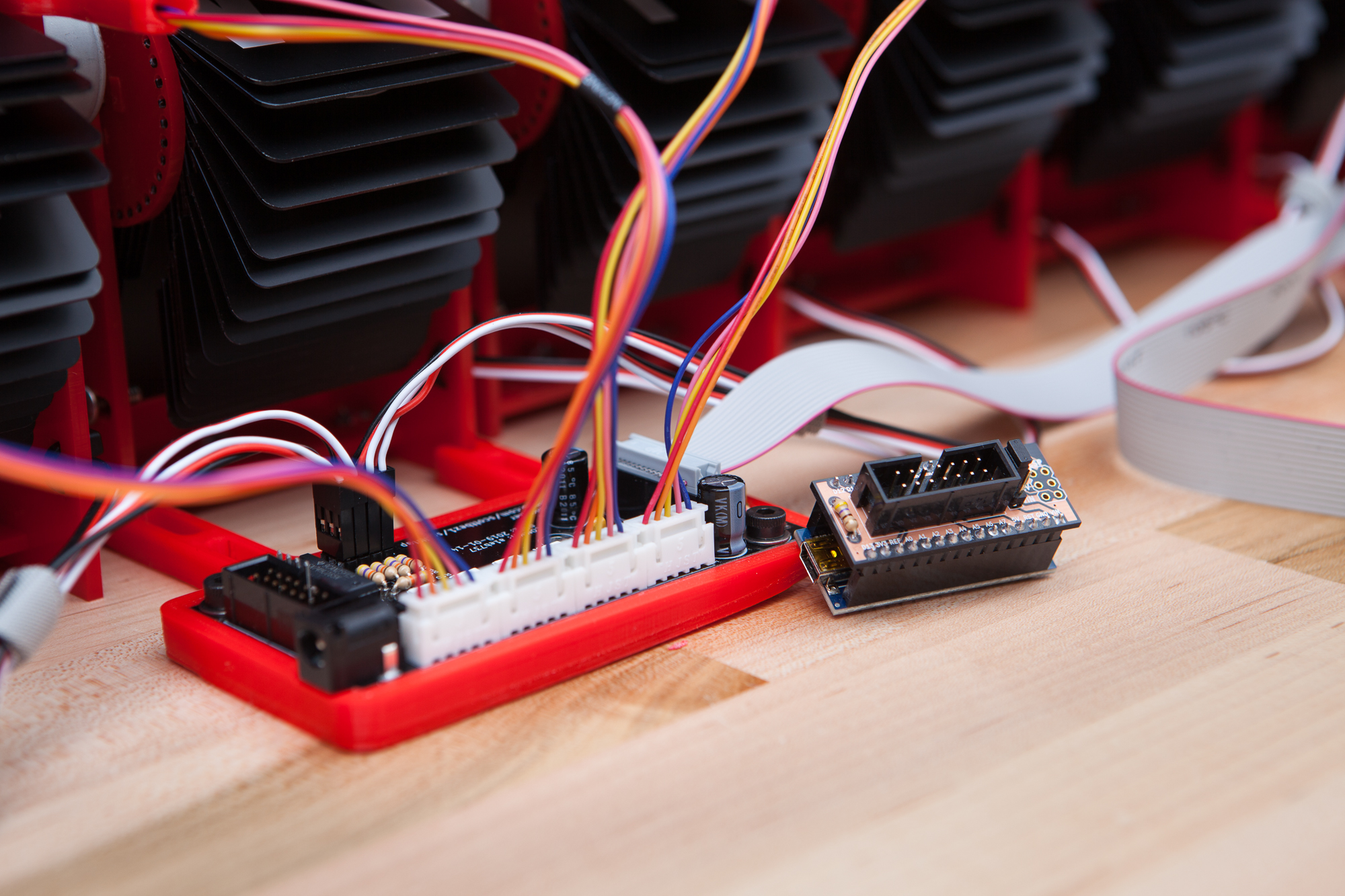
The control board is designed to sit on top of an Arduino Uno, plugging directly into its programming header and a few digital pins on the side. This is convenient, but without the Uno connected it leaves some awkward stray pins sitting down below the PCB. And with multiple driver boards chained it also puts them at an uneven level and makes it awkward to mount the circuit boards.
I took a different approach, taking advantage of the expansion headers on either side. The “input” header has all of the pins needed to communicate with the board: the SPI pins for the motor drivers, the latch pin for the sensors’ shift register, the LED data pin, and power for all components. I just needed a convenient way to plug into it.
I ended up designing another split-flap “shield” for the Arduino Nano. The Nano is functionally identical to the Uno, sharing the same ATmega328P as its brain but in a smaller form factor that’s easier to hide behind the display. The shield attaches directly on top of the Arduino Nano with female headers, and provides a 7×2 female IDC connector which connects directly to the driver board with a short cable. It also includes a jumper header that allows the microcontroller to be powered directly by the 12V supply used for the module motors.
This is a stop-gap. My eventual goal is to build another shield for use with a WiFi enabled microcontroller such as an ESP8266 or ESP32. But that’s a project for another day.
Assembly
Once the laser-cut enclosures had shipped, the flap characters were applied, and the electronics were fully soldered, it was time to combine all of the pieces and create the finished split-flap displays!
Making the Spool
First on the docket is the spool. The spool is composed of seven laser-cut parts: four “struts” which make up the spool’s center axis, two endcaps which have the pivot holes for the flaps themselves, and a retaining wall for the idler bolt. The interior of the spool contains a single M4-10 screw which provides the axis for the idle-side of the spool, and is retained with a captive nut on the idler end-cap. All of the spool’s parts are friction-fit, including the sensor magnet that indicates the spool’s home position.
Before anything else the magnets needed to be press-fit into the motor-side end cap. After testing with the sensors to make sure they were oriented right, I placed the magnets on top of a flat head screw which I mounted in my drill press. The magnets were inserted carefully from the outside face, after using a countersink to slightly bevel the mounting hole. On my modules the magnet hole was a little too tight, so I ended up sanding the holes slightly larger. (I also submitted a pull request to hopefully fix that issue for the future.)
The acrylic is a little temperamental and was not tight enough to hold together on all modules, so I decided to glue the spools. I used a few dabs of cyanoacrylate glue applied with a toothpick on the ends, leaving 24 hours to cure for each side. This effectively locks the idler bolt inside the spool, though thankfully a hex key can still fit through the motor shaft opening if it ever needs to be tightened.
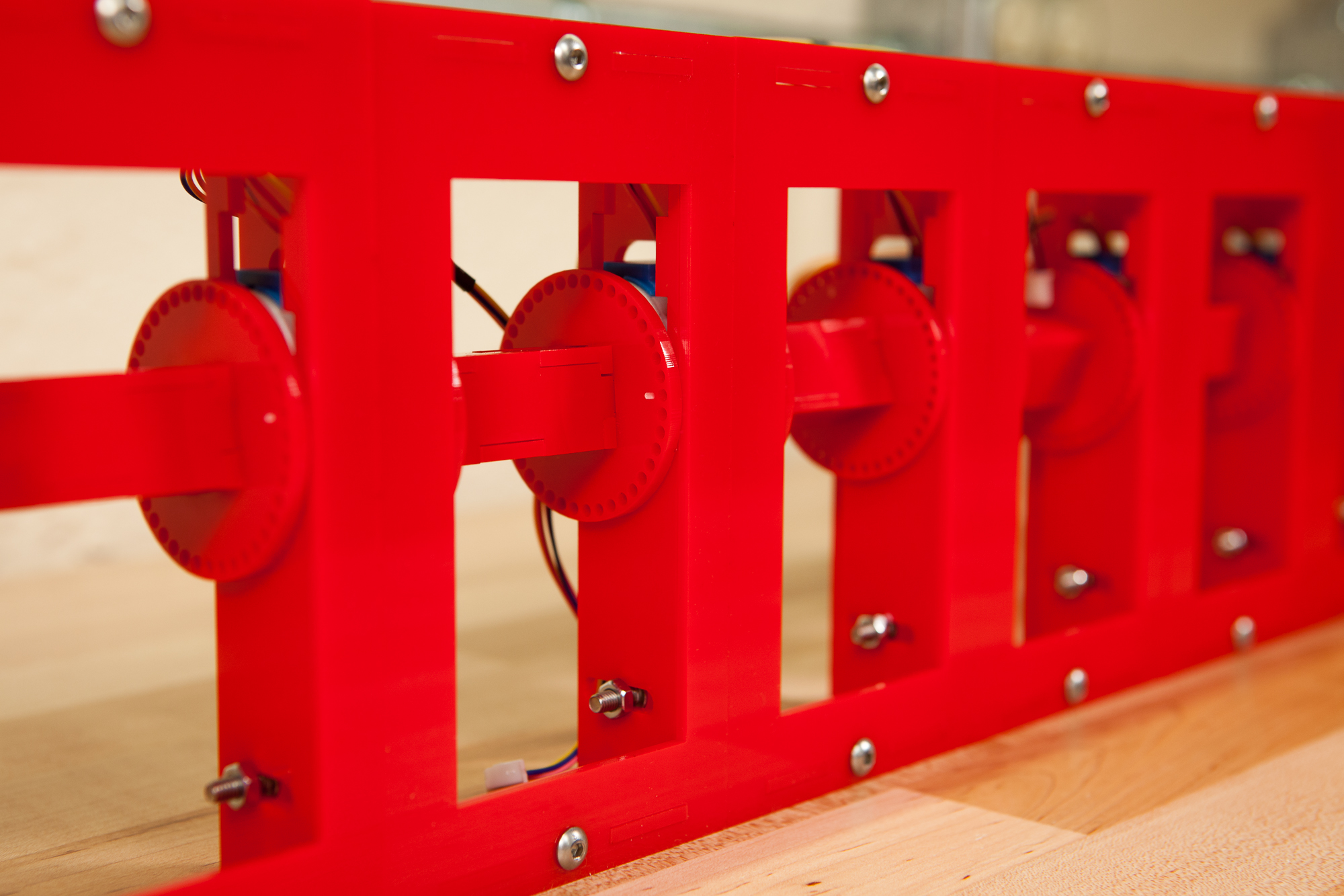
Bolting Up the Enclosure
While the glue on the spools was curing I set to assembling the rest of the enclosure.
I started with the electronics. Each module needs a 28BYJ-48 motor and a sensor PCB, both affixed to the left side of the enclosure with M4-10 button head screws. Both of the bolts go from the inside of the module to the outside and are secured with M4 nuts.
All of the enclosure panels are free-fit and simply slot into place with tabs. They are then restrained with more M4 bolts which thread into captive nuts placed in the top and bottom connector pieces. The entire assembly comes together in a matter of minutes, sans the left enclosure panel.
Once the spools were fully cured it was time to add them to their module. This was by far the most nerve-wracking part of the build, as the motor shaft hole on the spool was very tight and it would be difficult to remove the spool from the shaft once they had been joined. For a few spools I ended up lightly sanding the cutout for a smoother fit, but otherwise it was just a little bit of wiggling and elbow grease and the spool was fully attached to its motor.
To complete the enclosure the left enclosure panel with motor and spool in tow had to be mated to the rest of the enclosure shell. The trick is that the spool is meant to fit through the front panel, so the side panel could not slide on straight. Instead, I slid the panel on at an angle and with a quick tug on the spool the whole assembly shifted and fell into place. After applying the last two retaining screws to the left side, the enclosure assembly was complete.
Spooling Up the Flaps
Well, almost complete. The final step is to insert all 40 flaps into the spool.
One of my more inspired contributions to Scott’s project was adding a small etched indicator to the inside of the spool. This indicates the “home” flap, or the top flap for the first letter in the array. In my case the home flap was the top of the blank (space) character and the bottom of ‘A’. It’s critical to place the ‘home’ flap in the correct position in the spool, otherwise the hall effect sensor will not find the correct home position for the module.
The spool itself is barely wider than the main body of the flaps, so to get the flaps spooled up requires a bit of finesse. With one thumb on the base of the card, one pin needs to be inserted to the first side of the spool. The flap is then bent until it’s just narrow enough to fit the second pin into the other side, and then relaxed so it rests straight in the spool and the process is repeated another 39 times until all flaps are in place. It takes a few attempts but once you figure out the process it’s quick. It only becomes tricky for the last two or three flaps, where the flaps already on the spool start getting in the way.
Calling Audibles
At this point the modules were fully assembled, spooled up, and ready to go! Or, at least, they should have been. There were two small issues with the design that needed attention.
First was the axial slop for the 28BYJ-48 motor. Each motor had between 0.5 – 1.5 mm of play along its axis, causing the flap spool to wiggle left to right inside the front window. Once in awhile this would cause the spool to bind as the flaps would shift sideways and hit the edges of the front panel. To fix the issue I bought some nylon washers to act as plain bearings for the idler side of the spool, pushing the spool tight against the motor. This slop varied so I could have gotten away with not applying bearings washers to some of the modules, but while I was at it I figured I should just add them to all.

The other change had to do with the motor wires. Although I had modified the enclosure to add zip-tie holes for wire management the built-in motor wires were too short to use them and still reach the ports on the driver boards. This is an issue because stray motor wires have a tendency to fall into the moving flap spool and gum up the works.
My solution was a small 3D printed guide arm that clips onto the back of the motor mounting window. The clip’s “tunnel” supports the motor’s wires until they pass behind the flaps. The wires enter the guide through a small slit and are then retained with a piece of Kapton tape. This keeps the wires safely away from the spool while it’s spinning and requires no modifications to the enclosure itself.
Firmware Programming
With the split-flap display fully assembled, the final step is to upload the firmware to the microcontroller to make everything work. The task is, in theory, simple: take a letter input and then move the split-flap module’s motor until it displays the matching pair of flaps. Though how we (quite literally!) get from ‘A’ to ‘B’ is going to require a bit of thought.
Thankfully, again, Scott has already tackled this problem for us, and written an Arduino-compatible firmware that takes simple text inputs over the serial interface and translates them into movement commands for the split-flap modules.
Firmware Configuration
Before I can compile Scott’s firmware I need to set some configuration options. Although he has some options configured with a PlatformIO build file, we’re going to go down the list and set each option ourselves. Here’s my configuration for my 8-module display, based off of the latest firmware-related commit (82b94e3).
-DNUM_MODULES=8
-DSPI_IO=true
-DREVERSE_MOTOR_DIRECTION=false
-DNEOPIXEL_DEBUGGING_ENABLED=true
-DSSD1306_DISPLAY=false
-DINA219_POWER_SENSE=false
In classic embedded C form there are a number of preprocessor definitions which change the program’s behavior. In this case I set the total number of modules to 8 and enabled the SPI interface for talking to the driver board (as compared to using the board’s output pins directly with transistors). All of the accessories are disabled with the exception of the addressable LEDs on the control board, which are useful for debugging. These options can either be passed in the PlatformIO configuration file or altered by hand in the config header.
The firmware also uses a Python script to generate an array of pre-calculated time periods for the modules’ acceleration curves. The default settings were a bit aggressive for my setup and were causing the motors to stall during rapids. I re-generated the acceleration header using a MIN_PERIOD_MICROS setting of 1400 in place of the default 1200, which solved the stalling issue.
With all of the options set, I compiled the firmware using the Arduino IDE and the Arduino Uno/Nano board option, and uploaded it to the microcontroller. Immediately after reset the control boards’ LEDs flickered through a startup animation and the modules’ flap spools began to spin. We have liftoff!
Display Tests
Now that the displays are up and running it’s time to put them to work and display some text!
Because I’m using Scott’s embedded firmware I’m also going to be using his split-flap software script for these tests. Per Scott’s own notes the software is still in “beta” so it’s a little rough around the edges, but it’ll work fine for a test run..
demo.py
The included demo.py file in the software directory of the repository selects from a list of 4 letter animal names to show on the split-flap displays, sends the string’s ‘move’ command to the microcontroller, then waits for 10 seconds and repeats.
Upon running the demo the script will prompt the user for the serial port to which the microcontroller is attached, then jump straight into the output loop. This continues until the script is interrupted or closed.
This demo is a great first look at what the displays can do, although as-written it’s limited to four modules. For our next test, let’s up the ante and expand this to 8 modules.
terminal.py
I created this next script myself, extending Scott’s split-flap module implementation. It takes a text string from the command line as input and sends it directly to the display. It also does uppercase/lowercase translation for ease of use.
Much of my enjoyment of the display so far has been typing in various things and seeing words slowly flap into position. It works!
Shelf Mounting
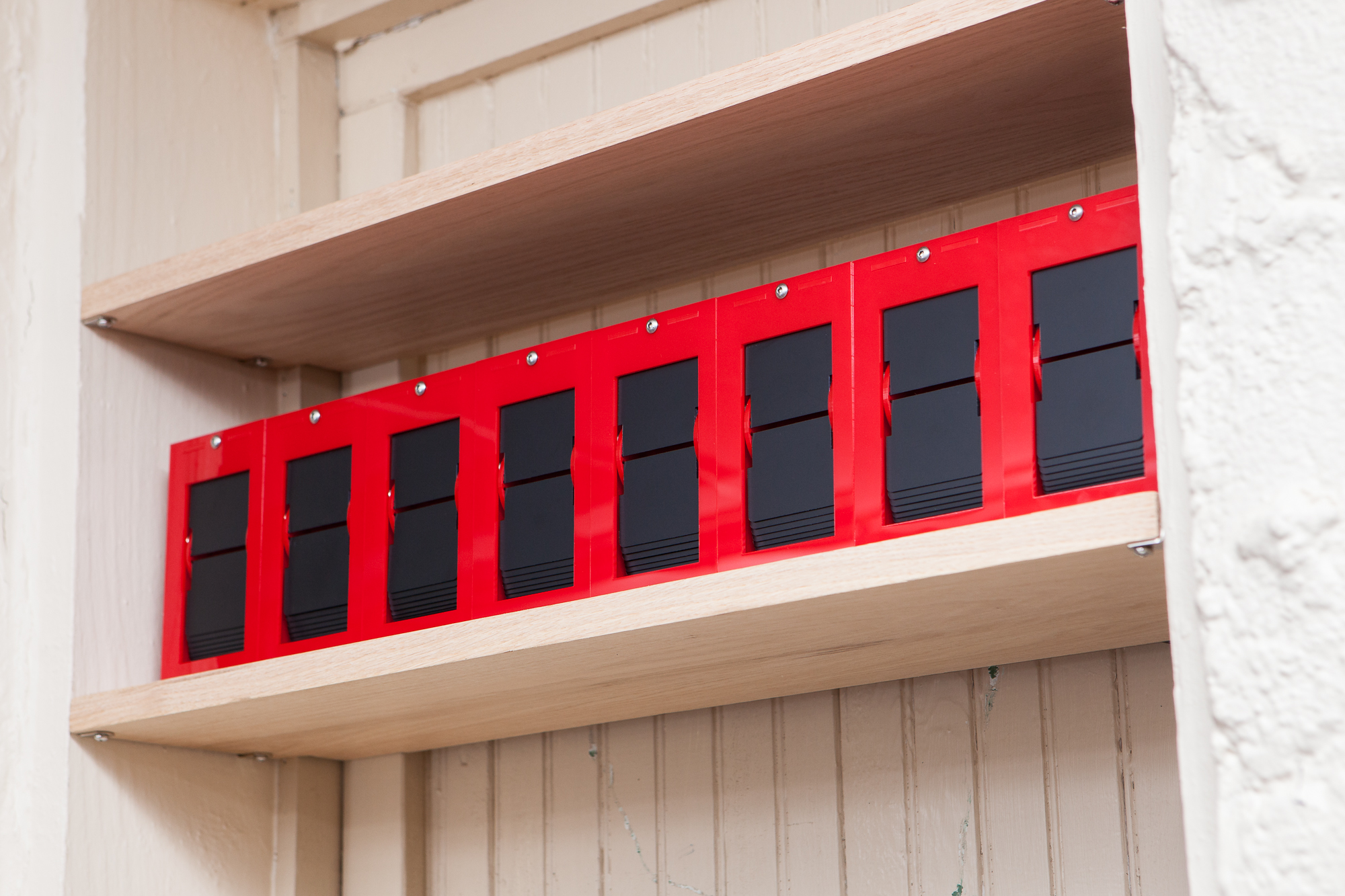
Now that the display is running, the “final” step is to move it from its temporary home on the workbench into its permanent home on a shelf.
In the original design each module is a separate component. To create the completed display, the modules are linked together with short “connector” pieces that slot into place at the top and bottom of each side. These connectors are made from the same laser-cut material as the rest of the module and are retained by the front panel.
Unfortunately one side effect of my changes to the CAD design is that the connector pieces were cut ever so slightly too narrow. This means the front enclosure pieces interfere and cause the display to bow inwards (towards the back of the modules). To replace them, I designed my own 3D printed mounting brackets.
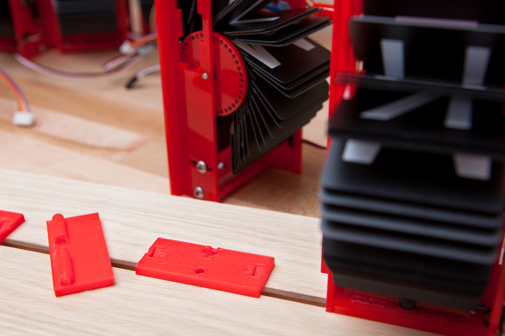
Created in OpenSCAD alongside the rest of the parts, these mounts fit neatly just underneath the bottom piece of the enclosure. Each mount has cutouts to accommodate the nuts and bolts holding everything together, and includes an extruded boss on the underside to fit into a T-slot track. A single corresponding M4 T-nut fits between these bosses and holds the module in place.
Compared to using individual brackets attached with screws, the T-slot is an easy way to keep all of the modules straight and aligned with minimal setup. It also allows me to change the number of modules in the display while still having the freedom to rearrange them on the shelf (as far as the wiring will allow).
Future Improvements
The display may be working but there is always more to be done. Still on the agenda:
- Rewriting the microcontroller firmware to be more extensible
- Creating an ESP8266 adapter (“shield”)
Connecting the display to an API’s output– Done!
My eventual goal is to detach the display from the tethered USB connection and have it run on its own, receiving commands and text strings over WiFi. But I think this is enough of a project for one day nine months.
Originally I had planned for this to be a quick project, but that idea went out the door as soon as I started making some “small” changes to the CAD design. Six months of planning and building combined with three months of procrastinating video editing and writeup means that I am itching to move on to something new.
Parts List
Want to build your own set of split-flap displays? Here’s the (hopefully) complete parts list. I’d also recommend checking out Scott’s v0.5 ordering guide and assembly instructions, as well as the documentation in the repository.
Please note that some of these are affiliate links which help fund the content on this site. Thank you for your support!
Enclosure
- Laser-cut enclosure from Ponoko in red acrylic
- 11x M4-10 Stainless Steel Button Head Hex Drive Screws
- 11x M4-10 Zinc-Plated Steel Hex Nut
- 4 mm Diameter Neodymium Magnet (spool home)
- M4 x 1 mm Black Nylon Washer (idler side)
These numbers are per split-flap module. I used a total of 8 modules in my display.
Electronics
Modules
- 12V 28BYJ-48 Stepper Motor
- Split-Flap Sensor PCB (x4)
- Hall Effect Sensor Unipolar Switch AH3369Q
- 0.1″x3 Right-Angle Pin Header
- Custom 3D-Printed Motor Wire Guide (Overture Red PLA)
Each module needs its own motor and home sensor. I used a total of 8 modules in my display, and thus ordered 2 sets of sensor PCBs.
Control Board
- Split-Flap Control Board PCB
- MIC5842 Latched Output Drivers (U2, U4)
- 74HC165N Shift Register (U3)
- WS2812B Addressable LEDs (U5, U6, U7, U8)
- JST XH 5-Pin Connector Sockets (P1, P2, P3, P4)
- 0.1″ Pin Header, 1×4 (P6, P7, P8) (cut from a single long strip)
- IDC Header 14 Position (2×7) (J1, J2)
- 2.1 mm Barrel Jack Connector (CON1)
- 3 mm Yellow LED (D1)
- 3 mm Green LED (D2)
- 100 uF Electrolytic Capacitor (C1, C3)
- 0.1 uF Ceramic Capacitor (C2)
- 2.2K Ohm 1/4W Resistor (R1)
- 47K Ohm 1/4W Resistor (R3, R4, R5, R6, R10)
- 220 Ohm 1/4W Resistor (R7)
- 470 Ohm 1/4W Resistor (R9)
Each control board will drive 4 split-flap modules. I built 2 control boards for my project. All components are through-hole with the exception of the WS2812B LEDs.
One IDC connector cable was used to connect the two control boards together.
Microcontroller
- Arduino Nano
- Split-Flap Nano Breakout Board (Custom)
- 2x 0.1″ 15 Position Female Header
- 2x 0.1″ 15 Position Male Header (cut from a single long strip)
- 470 Ohm Resistor
- IDC Connector Cable, 2×7 – 18″
Only one microcontroller is needed to drive all of the split-flap modules.
Flaps
- Blank Split-Flap Display Flaps, Die-Cut (Matte Black)
- Oracal 631 Roll of Matte White Vinyl (12″ x 15′)
- YRYM HT Clear Vinyl Transfer Paper Tape Roll (12″ x 50′)
Each package contains more than 160 flaps, which is enough for 4 modules of 40 flaps each. I used 8 modules in my display, ordering 2 packs of flaps and 2 rolls of vinyl.
The roll of transfer tape covered both sets of flaps with plenty (20’+) to spare. The vinyl letters were cut out using my Silhouette Cameo 3 vinyl cutter.
If you do not have a vinyl cutter, Scott recommends using sheets of pre-cut vinyl letters.
Mounting
- 1×8 Oak Board (for shelf)
- 4x Shelf Support Pegs, L-Bracket Style
- 4x #8 1/2″ Pan-Head Zinc Wood Screws
- T-Slot Router Bit for 1/2″ Hex Bolt (fits M4 nuts as well)
Module Mounts
- 3D-Printed T-Slot Module Mount (Overture Red PLA)
- 1x M4-14 Socket Head Cap Screw
- 1x M4 Sliding T-Nut
These numbers are per split-flap module. I used a total of 8 modules in my display.
Control Board Mounts
- 3D-Printed Control Board Mount (Overture Red PLA)
- 3x M4-8 Socket Head Cap Screw
- 3x M4 Stainless Steel Washer
- 3x M4-6 Threaded Brass Insert
- 2x #4 1/2″ Pan-Head Zinc Wood Screws
Microcontroller Mount
- Custom 3D-Printed Arduino Nano Mount (Overture Red PLA)
- 2x #4 1/2″ Pan-Head Zinc Wood Screws
The microcontroller just sits in its box and is not adhered in any way.